background image

Document Change Notice

300020-C Rev. 00

71


Starting the BCC

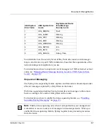
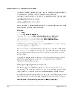
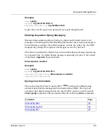
To start the BCC interface, log in to the Technician Interface and enter the 

bcc


command at the prompt:

Router1> 

bcc

     Welcome to the Bay Command Console!

     * To enter configuration mode, type config

     * To list all system commands, type ?

     * To exit the BCC, type exit

bcc>

If you need more information about how to log on to a Bay Networks router, see 
Using Technician Interface Software.

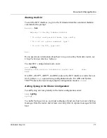
To enter BCC configuration mode, enter:

bcc> 

config

Reading configuration information, please wait . . . done.

box# 

On AN®, ANH™, ARN™, and BN® routers, the BCC interface returns the root 
level prompt, 

box#

, upon entering configuration mode. For ASN and System 

5000™ routers, the root-level prompt in configuration mode is 

stack#.

Adding Syslog to the Router Configuration

To add Syslog services globally to the router configuration, enter:

box# 

syslog

syslog# 

To enable Syslog services, you must configure at least one host to receive Syslog 
messages from the router, and at least one entity filter to capture messages for that 
host. 

Содержание BayRS

Страница 1: ...BayRS Version 13 10 Document Change Notice Part No 300020 C Rev 00 November 1998 BayRS Version 13 10 Site Manager Software Version 7 10 BCC Version 4 10 ...

Страница 2: ...ense agreement that may pertain to or accompany the delivery of this computer software the rights of the United States Government regarding its use reproduction and disclosure are as set forth in the Commercial Computer Software Restricted Rights clause at FAR 52 227 19 Statement of Conditions In the interest of improving internal design operational function and or reliability Bay Networks Inc res...

Страница 3: ...any third party the Software or any information about the operation design performance or implementation of the Software and user manuals that is confidential to Bay Networks and its licensors however Licensee may grant permission to its consultants subcontractors and agents to use the Software at Licensee s facility provided they have agreed to use the Software only in accordance with the terms o...

Страница 4: ... expiration of the Bay Networks copyright those restrictions relating to use and disclosure of Bay Networks confidential information shall continue in effect Licensee may terminate this license at any time The license will automatically terminate if Licensee fails to comply with any of the terms and conditions of the license Upon termination for any reason Licensee will immediately destroy or retu...

Страница 5: ...to RS 232 Raise DTR Order No 7118 18 15 Pin D Sub to RS 232 V 25bis Order No 7119 19 15 Pin D Sub to V 35 V 25bis Order No 7120 20 15 Pin D Sub to V 35 Raise DTR Order No 7121 21 44 Pin D Sub to V 35 Raise DTR Order No 7137 22 44 Pin D Sub to RS 232 Raise DTR Order No 7138 24 44 Pin to V 35M Order No 7159 26 RS 232 Pass Through 15 Pin to RS 232 Order No 7218 28 44 Pin D Sub to V 35 Leased Line or ...

Страница 6: ...der No 7945 48 50 Pin to F V 35 Synchronous Pass Through Order No 7946 49 Configuring PPP Services 50 Setting the Maximum Receive Unit MRU 50 Disabling RFC 1661 Compliance 52 PPP Line Parameters 53 Configuring Data Encryption Services 55 Using Encryption with Dial Services 55 Configuring Frame Relay Services 56 Calculating the MTU Size for Frame Relay Connections 56 Using Technician Interface Soft...

Страница 7: ...work with Name Server Address Origin Parameter Set to RADIUS 9 Figure 4 Run Window 11 Figure 5 IP Configuration Window 12 Figure 6 More Info IP Configuration Window 13 Figure 7 Syslog and syslogd Operations 59 Figure 8 Router Event Message Filtering for One Host 61 Figure 9 Syslog Message Encapsulation 65 Figure 10 Syslog Message Composition 66 Figure 11 BCC Configuration Hierarchy for Syslog Serv...

Страница 8: ......

Страница 9: ...Documentation 1 Table 2 Syslog Parameters box or stack syslog 86 Table 3 Parameters of log host box or stack syslog log host 86 Table 4 Parameters of filter box or stack syslog log host filter 87 Table 5 Version 13 10 Boot and Diagnostic PROM Revisions 89 ...

Страница 10: ......

Страница 11: ...nd which are affected by sections in this document change notice Text Conventions This guide uses the following text conventions angle brackets Indicate that you choose the text to enter based on the description inside the brackets Do not type the brackets when entering the command Example If the command syntax is ping ip_address you enter ping 192 32 10 12 bold text Indicates command names and op...

Страница 12: ...faces alerts you can enter either show ip interfaces or show ip interfaces alerts ellipsis points Indicate that you repeat the last element of the command as needed Example If the command syntax is ethernet 2 1 parameter value you enter ethernet 2 1 and as many parameter value pairs as needed italic text Indicates file and directory names new terms book titles and variables in command syntax descr...

Страница 13: ...parator Shows menu paths Example Protocols IP identifies the IP option on the Protocols menu vertical line Separates choices for command keywords and arguments Enter only one of the choices Do not type the vertical line when entering the command Example If the command syntax is show ip alerts routes you enter either show ip alerts or show ip routes but not both DNS domain name server IP Internet P...

Страница 14: ...og html and is divided into sections arranged alphabetically The CD ROMs section lists available CDs The Guides Books section lists books on technical topics The Technical Manuals section lists available printed documentation sets Make a note of the part numbers and prices of the items that you want to order Use the Marketing Collateral Catalog description link to place an order and to print the o...

Страница 15: ...e Configuring and Managing Routers with Site Manager Configuring and Troubleshooting Bay Dial VPN Networks Configuring AppleTalk Services Configuring APPN Services Configuring ATM DXI Services Configuring ATM Half Bridge Services Configuring ATM and MPLS Services Configuring BaySecure FireWall 1 Configuring BayStack Remote Access Configuring Bridging Services Configuring BSC Transport Services Con...

Страница 16: ...rvices Configuring IPX Services Configuring L2TP Services Configuring LLC Services Configuring LNM Services Configuring OSI Services Configuring Polled AOT Transport Services Configuring PPP Services Configuring RADIUS Configuring RMON and RMON2 Configuring SDLC Services Configuring SMDS Configuring SNMP BootP DHCP and RARP Services Configuring Traffic Filters and Protocol Prioritization Configuri...

Страница 17: ...ork Managing Routers Using the HTTP Server Quick Starting Routers Troubleshooting Routers Upgrading Routers to BayRS Version 13 xx Using Technician Interface Scripts Using Technician Interface Software Using the Bay Command Console Writing Technician Interface Scripts Table 1 Version 13 10 7 10 Documentation continued Document Title Revised Book for 13 10 7 10 Affected by Section in DCN ...

Страница 18: ... as an L2TP network server LNS to obtain NSAs from either the LNS or a RADIUS server To use the NSA feature users at remote sites configuring their dial up connections in Windows 95 Windows 98 or Windows NT must specify that their connections will use server assigned name server addresses indicating that a remote server provides NSAs Users specify this in the Dial Up Networking TCP IP Settings win...

Страница 19: ...ame server DNS and WINS name server addresses also called NetBIOS name server addresses or NBNS addresses Instead when a user dials in the LNS or RADIUS server automatically assigns name server addresses for the connection If a name server address changes the network administrator can make a single modification at the LNS or RADIUS server site every remote user is not required to go back into the ...

Страница 20: ...sses use the DNS and NetBIOS NSAs that you set in Site Manager You set these addresses via the Site Manager parameters Primary DNS Address Secondary DNS Address Primary NBNS Address and Secondary NBNS Address RADIUS If you set the Name Server Address Origin parameter to RADIUS users who dial in to the LNS on this slot obtain NSAs from a RADIUS server provided that they have configured their TCP IP...

Страница 21: ...ddress Origin parameter is set to Local in Site Manager on the LNS at the corporate site The other Site Manager parameters related to this NSA feature on the LNS Primary DNS Address Secondary DNS Address Primary NBNS Address and Secondary NBNS Address are set to the addresses of name servers on the corporate network DNS1 DNS2 NBNS1 and NBNS2 When users at remote hosts A B and C make dial up connec...

Страница 22: ...me Server Address Origin parameter is set to RADIUS in Site Manager on the LNS at the corporate site The RADIUS server on the corporate network specifies that users dialing in from remote hosts in Engineering should use Eng DNS1 Eng DNS2 Eng NBNS1 and Eng NBNS2 as their primary and secondary name servers The RADIUS server on the corporate network specifies that users dialing in from remote hosts i...

Страница 23: ...ote hosts Fin host A and Fin host B make dial up connections to the corporate network those connections use Fin DNS1 Fin DNS2 Fin NBNS1 and Fin NBNS2 as primary and secondary name servers Figure 3 Network with Name Server Address Origin Parameter Set to RADIUS Fin host A ISP network Corporate network TMS LAC LNS RADIUS server Fin DNS 1 Fin NBNS 1 Fin DNS 2 Fin NBNS 2 Eng DNS 2 Eng NBNS 1 Eng NBNS ...

Страница 24: ... L2TP Configuration The L2TP Configuration List window opens 5 Set the Name Server Address Origin parameter If you set this parameter to Local you must also set the following parameters Primary DNS Address Secondary DNS Address Primary NBNS Address Secondary NBNS Address If you set this parameter to Radius you must also set the following parameters RADIUS Primary Server IP Address RADIUS Primary S...

Страница 25: ... see which NSAs the LNS or RADIUS server assigned to a particular user complete the following steps at the remote user s PC 1 Choose Start Run The Run window opens Figure 4 Figure 4 Run Window 2 At the Open prompt enter winipcfg The IP Configuration window opens Figure 5 ...

Страница 26: ... The More Info IP Configuration window opens Figure 6 The DNS Servers field lists the primary and secondary DNS server addresses assigned by the server Click on the button to see the secondary server address The Primary WINS Server and Secondary WINS Server fields list the primary and secondary NBNS addresses if any ...

Страница 27: ...Document Change Notice 300020 C Rev 00 13 Figure 6 More Info IP Configuration Window ...

Страница 28: ...want to use the NSA feature If this feature is disabled remote hosts use the DNS and NBNS addresses configured on their individual dial up connections Set to Local if you want all remote hosts to use the DNS and NBNS addresses that you configure in Site Manager Set to RADIUS if you want remote hosts to obtain DNS and NBNS addresses from a RADIUS server MIB Object ID 1 3 6 1 4 1 18 3 5 23 2 1 23 Pa...

Страница 29: ...ault None Options Any valid IP address Function If the Name Server Address Origin parameter is set to Local the Primary NBNS Address parameter specifies the address of the primary NetBIOS name server NBNS that every remote host should use Instructions Enter the IP address of the primary NBNS MIB Object ID 1 3 6 1 4 1 18 3 5 23 2 1 26 Parameter Secondary NBNS Address Path Configuration Manager Prot...

Страница 30: ...b to V 35 Leased Line or V 25bis Order No 7220 15 Pin D Sub to RS 232 Order No 7255 15 Pin D Sub to V 28 Order No 7256 44 Pin D Sub to RS 232 Leased Line or V 25bis Order No 7826 RS 232 Pass Through 44 Pin to RS 232 Order No 7833 V 35 Pass Through 44 Pin to V 35 Order No 7834 44 Pin D Sub to V 28 Order No 7837 50 Pin to V 35 Order No 7932 50 Pin to V 35 Raise DTR Order No 7933 50 Pin to RS 232 Ord...

Страница 31: ...nd Data Set Ready 6 6 Data Set Ready Signal Ground 7 7 Signal Ground Data Terminal Ready 8 20 Data Terminal Ready Data Carrier Detect 9 8 Data Carrier Detect Send Timing 10 15 Send Timing Receive Timing 11 17 Receive Timing Terminal Timing 12 24 Terminal Timing Internal Wire Connections Pin 7 30 31 Pin 13 38 Pin 14 39 4 57 m Pin 13 Pin 1 Pin 25 Pin 14 25 position D sub plug with M 3 jack screws gr...

Страница 32: ...ment Timing DCE Source 4 15 Transmitter Signal Element Timing DCE Source Request to Send 6 4 Request to Send Clear to Send 8 6 Data Set Ready Data Carrier Detect 10 22 Ring Indicator Receiver Signal Element Timing DCE Source 12 17 Receiver Signal Element Timing DCE Source Received Data 14 3 Received Data Internal Wire Connections Pin 1 7 Pin 4 20 Data Terminal Ready Pin 8 Pin 15 Pin 9 Pin 13 Pin 1...

Страница 33: ...g DCE Source 4 15 Transmitter Signal Element Timing DCE Source Request to Send 6 4 Request to Send Clear to Send 8 5 Clear to Send Data Carrier Detect 10 6 Data Set Ready Receiver Signal Element Timing DCE Source 12 17 Receiver Signal Element Timing DCE Source Received Data 14 3 Received Data Internal Wire Connections Pin 1 7 Pin 4 20 Data Terminal Ready Pin 8 Pin 15 Pin 9 Pin 13 Pin 1 Pin 25 Pin ...

Страница 34: ...d Timing B Request to Send 6 C Request to Send Clear to Send 8 D Clear to Send Data Carrier Detect 10 E Data Set Ready Serial Clock Receive 11 X Receive Timing B Serial Clock Receive 12 V Receive Timing A Receive Data 13 T Receive Data B Receive Data 14 R Receive Data A Internal Wire Connections Pin 1 7 Pin C H Data Terminal Ready Pin 8 Pin 15 Pin 9 Pin 1 15 ft 4 57 m B D R T V X A E C H P S Y AA ...

Страница 35: ...B Request to Send 6 C Request to Send Clear to Send 8 E Data Set Ready Data Carrier Detect 10 J Ring Indicator Serial Clock Receive 11 X Receive Timing B Serial Clock Receive 12 V Receive Timing A Receive Data 13 T Receive Data B Receive Data 14 R Receive Data A Internal Wire Connections Pin 1 7 Pin C H Data Terminal Ready Pin 8 Pin 1 Pin 15 Pin 9 15 ft 4 57 m B J R T V X A E C H P S Y AA 15 posit...

Страница 36: ...37 Industry Interface Type V 35 V 10 and V 11 Pin 1 Pin 16 Pin 31 Pin 15 Pin 30 Pin 44 15 ft 4 57 m B D J R T V X A C E H P S U W Y AA 44 position D sub plug with screw locks ground shield connected to backshell 34 position V 35 plug with screw jack retainers ground shield connected to backshell CAB0018A ...

Страница 37: ...t Ready Data Terminal Ready 8 H Data Terminal Ready Data Carrier Detect 9 J Ring Indicator VTT 40 U Terminal Timing A VTT 39 W Terminal Timing B Signal Ground 19 B Signal Ground VST 32 Y Send Timing A VST 31 AA Send Timing B VRT 34 V Receive Timing A VRT 33 X Receive Timing B VRD 37 R Receive Data A VRD 35 T Receive Data B VSD 38 P Send Data A VSD 36 S Send Data B Internal Wire Connections Pin 7 1...

Страница 38: ...TR Order No 7138 Industry Interface Type RS 232 C 15 ft 4 57 m Pin 13 Pin 1 Pin 25 Pin 14 25 position D sub plug with screw locks ground shield connected to backshell Pin 1 Pin 16 Pin 31 Pin 15 Pin 30 Pin 44 44 position D sub plug with screw locks ground shield connected to backshell CAB0019A ...

Страница 39: ... Send 4 4 Request to Send Clear to Send 5 5 Clear to Send Data Set Ready 6 6 Data Set Ready Signal Ground 7 7 Signal Ground Data Terminal Ready 8 20 Data Terminal Ready Data Carrier Detect 9 22 Ring Indicator Send Timing 10 15 Send Timing Receive Timing 11 17 Receive Timing Transmitter Signal Element Timing 12 24 Transmitter Signal Element Timing Internal Wire Connections Pin 7 19 20 Pin 13 28 Pin...

Страница 40: ...stry Interface Type V 35 V 10 and V 11 10 ft 3 05 m Pin 1 Pin 16 Pin 31 Pin 15 Pin 30 Pin 44 B D F R T V X A C E H P S U W Y AA 44 position D sub plug with screw locks ground shield connected to backshell 34 position V 35 plug with screw jack retainers ground shield connected to backshell CAB0031B ...

Страница 41: ...eady Data Terminal Ready 8 H Data Terminal Ready Data Carrier Detect 9 F Data Carrier Detect VTT 40 U Terminal Timing A VTT 39 W Terminal Timing B Signal Ground 19 B Signal Ground VST 32 Y Send Timing A VST 31 AA Send Timing B VRT 34 V Receive Timing A VRT 33 X Receive Timing B VRD 37 R Receive Data A VRD 35 T Receive Data B VSD 38 P Send Data A VSD 36 S Send Data B Internal Wire Connections Pin 7...

Страница 42: ... Transmit Clock 4 15 Transmit Clock Data Set Ready 6 8 Data Carrier Detect Data Carrier Detect 10 4 Clear to Send Receive Clock 12 17 Receive Clock Received Data 14 2 Transmitted Data Internal Wire Connections Pin 1 7 Pin 4 5 Pin 6 8 Pin 6 20 Pin 3 4 12 Pin 8 Pin 1 Pin 15 Pin 9 Pin 13 Pin 1 Pin 25 Pin 14 15 ft 4 57 m 15 position D sub plug with locking posts ground shield connected to backshell 25...

Страница 43: ...Industry Interface Type V 35 V 10 and V 11 15 ft 4 57 m A C E H P S U W AA B D F R T V X Y 34 position V 35 plug with screw jack retainers ground shield connected to backshell CAB0106A Pin 1 Pin 16 Pin 31 Pin 15 Pin 30 Pin 44 44 position D sub plug with screw locks ground shield connected to backshell ...

Страница 44: ...VST 31 AA Send Timing B VRD 37 R Receive Data A VRD 35 T Receive Data B Data Set Ready 6 E Data Set Ready Data Terminal Ready 8 H Data Terminal Ready Request to Send 4 C Request to Send Clear to Send 5 D Clear to Send VTT 40 U Terminal Timing A VTT 39 W Terminal Timing B Frame Ground 1 A Frame Ground Data Carrier Detect 9 F Data Carrier Detect Signal Ground 19 B Signal Ground Internal Wire Connect...

Страница 45: ...urce 4 15 Transmitter Signal Element Timing DCE Source Request to Send 6 4 Request to Send Clear to Send 8 5 Clear to Send Carrier Detect 10 8 Carrier Detect Receiver Signal Element Timing DCE Source 12 17 Receiver Signal Element Timing DCE Source Received Data 14 3 Received Data Data Set Ready 15 6 Data Set Ready Internal Wire Connections Pin 1 7 Pin 4 20 Pin 8 Pin 1 Pin 15 Pin 9 Pin 13 Pin 1 Pin...

Страница 46: ...urce 4 15 Transmitter Signal Element Timing DCE Source Request to Send 6 4 Request to Send Clear to Send 8 5 Clear to Send Carrier Detect 10 8 Carrier Detect Receiver Signal Element Timing DCE Source 12 17 Receiver Signal Element Timing DCE Source Received Data 14 3 Received Data Data Set Ready 15 6 Data Set Ready Internal Wire Connections Pin 1 7 Pin 4 20 Pin 8 Pin 1 Pin 15 Pin 9 Pin 13 Pin 1 Pin...

Страница 47: ...Data Set Ready Data Terminal Ready 8 20 Data Terminal Ready Data Carrier Detect 9 8 Data Carrier Detect Send Timing 10 15 Send Timing Receive Timing 11 17 Receive Timing Transmitter Signal Element Timing 12 24 Transmitter Signal Element Timing Signal Ground 7 7 Signal Ground Internal Wire Connections Pin 7 19 20 Pin 13 28 Pin 14 29 Pin 1 Pin 16 Pin 31 Pin 15 Pin 30 Pin 44 Pin 13 Pin 1 Pin 25 Pin 1...

Страница 48: ...9 5 Clear to Send RTS 4 8 Data Carrier Detect Send Timing 10 17 Receive Timing Frame Ground 1 1 Frame Ground Signal Ground 7 7 Signal Ground Internal Wire Connections Pin 4 5 Pin 4 5 Pin 10 11 12 Pin 15 17 Pin 7 19 20 Pin 6 20 Pin 13 28 Pin 14 29 15 ft 4 57 m Pin 13 Pin 1 Pin 25 Pin 14 Pin 1 Pin 16 Pin 31 Pin 15 Pin 30 Pin 44 44 position D sub plug with screw locks ground shield connected to backs...

Страница 49: ...ry Interface Type V 35 V 10 and V 11 15 ft 4 57 m A C E H P S U W AA B D F R T V X Y 34 position V 35 plug with screw jack retainers ground shield connected to backshell CAB0106A Pin 1 Pin 16 Pin 31 Pin 15 Pin 30 Pin 44 44 position D sub plug with screw locks ground shield connected to backshell ...

Страница 50: ... Data B VRD 37 P Send Data A VRD 35 S Send Data B Request to Send 4 F Data Carrier Detect Data Carrier Detect 9 D Clear to Send VTT 40 V Receive Timing A VTT 39 X Receive Timing B Frame Ground 1 A Frame Ground Signal Ground 7 B Signal Ground Internal Wire Connections Pin 4 5 Pin C D Pin 32 34 40 Pin V Y Pin 31 33 39 Pin X AA Pin 7 19 20 41 42 Pin E H Pin 13 28 Pin 14 29 ...

Страница 51: ...ndustry Interface Type V 28 V 10 Pin 1 Pin 16 Pin 31 Pin 15 Pin 30 Pin 44 Pin 13 Pin 1 Pin 25 Pin 14 15 ft 4 57 m 25 position D sub plug with M 3 jack screws ground shield connected to backshell 44 position D sub plug with screw locks ground shield connected to backshell CAB0069B ...

Страница 52: ...quest to Send 4 4 Request to Send Clear to Send 5 5 Clear to Send Data Set Ready 6 6 Data Set Ready Data Terminal Ready 8 20 Data Terminal Ready Data Carrier Detect 9 8 Data Carrier Detect Send Timing 10 15 Send Timing Receive Timing 11 17 Receive Timing Transmitter Signal Element Timing 12 24 Transmitter Signal Element Timing Signal Ground 7 7 Signal Ground Internal Wire Connections Pin 7 19 20 P...

Страница 53: ...dustry Interface Type V 35 V 10 and V 11 15 ft 4 57 m A C E H P S U W AA B D F R T V X Y 34 position V 35 plug with screw jack retainers ground shield connected to backshell Pin 1 Pin 25 Pin 26 Pin 50 50 position 0 8 mm plug ground shield connected to internal shell CAB0070A ...

Страница 54: ...VST 16 AA Send Timing B VRD 43 R Receive Data A VRD 18 T Receive Data B Data Set Ready 6 E Data Set Ready Data Terminal Ready 8 H Data Terminal Ready Request to Send 4 C Request to Send Clear to Send 5 D Clear to Send VTT 45 U Terminal Timing A VTT 20 W Terminal Timing B Frame Ground 1 A Frame Ground Data Carrier Detect 9 F Data Carrier Detect Signal Ground 30 B Signal Ground Internal Wire Connect...

Страница 55: ...33 Industry Interface Type V 35 V 10 and V 11 15 ft 4 57 m A C E H P S U W Y AA B D J R T V X 34 position V 35 plug with screw jack retainers ground shield connected to backshell Pin 1 Pin 25 Pin 26 Pin 50 50 position 0 8 mm plug ground shield connected to internal shell CAB0071A ...

Страница 56: ... A VST 16 AA Send Timing B VRD 43 R Receive Data A VRD 18 T Receive Data B Data Set Ready 6 E Data Set Ready Data Terminal Ready 8 H Data Terminal Ready Request to Send 4 C Request to Send Clear to Send 5 D Clear to Send VTT 45 U Terminal Timing A VTT 20 W Terminal Timing B Frame Ground 1 A Frame Ground Data Carrier Detect 9 J Ring Indicator Signal Ground 30 B Signal Ground Internal Wire Connectio...

Страница 57: ...Data Set Ready Signal Ground 7 7 Signal Ground Data Terminal Ready 8 20 Data Terminal Ready Data Carrier Detect 9 8 Data Carrier Detect Send Timing 10 15 Send Timing Receive Timing 11 17 Receive Timing Terminal Timing 12 24 Terminal Timing Signal Ground 7 7 Signal Ground Internal Wire Connections Pin 7 30 31 Pin 13 38 Pin 14 39 15 ft 4 57 m Pin 13 Pin 1 Pin 25 Pin 14 25 position D sub plug with sc...

Страница 58: ...Clear to Send Data Set Ready 6 6 Data Set Ready Data Terminal Ready 8 20 Data Terminal Ready Data Carrier Detect 9 22 Ring Indicator Send Timing 10 15 Send Timing Receive Timing 11 17 Receive Timing Terminal Timing 12 24 Terminal Timing Signal Ground 7 7 Signal Ground Internal Wire Connections Pin 7 30 31 Pin 13 38 Pin 14 39 15 ft 4 57 m Pin 13 Pin 1 Pin 25 Pin 14 25 position D sub plug with screw...

Страница 59: ...a Request to Send 6 8 Data Carrier Detect Data Carrier Detect 10 4 Request to Send Transmit Clock 4 15 Transmit Clock Signal Ground 1 7 Signal Ground Internal Wire Connections Pin 6 8 Pin 4 5 Pin 3 4 12 Pin 15 17 Pin 1 7 Pin 6 20 Pin 8 Pin 1 Pin 15 Pin 9 15 ft 4 57 m Pin 1 Pin 13 Pin 14 Pin 25 15 position D sub plug with locking posts ground shield connected to backshell 25 position D sub receptac...

Страница 60: ...Carrier Detect Data Carrier Detect 9 4 Request to Send Send Timing 10 15 Send Timing Frame Ground 1 1 Frame Ground Signal Ground 7 7 Signal Ground Internal Wire Connections Pin 4 5 Pin 4 5 Pin 10 11 12 Pin 15 17 Pin 13 28 Pin 6 20 Pin 14 29 Pin 7 19 20 Pin 1 Pin 16 Pin 31 Pin 15 Pin 30 Pin 44 15 ft 4 57 m 44 position D sub plug with screw locks ground shield connected to backshell CAB0081A Pin 1 P...

Страница 61: ...ta Carrier Detect 9 C Request to Send VTT 40 Y Send Timing A VTT 39 AA Send Timing B Frame Ground 1 A Frame Ground Signal Ground 7 B Signal Ground Internal Wire Connections Pin 4 5 Pin C D Pin 32 34 40 Pin V Y Pin 31 33 39 Pin X AA Pin 13 28 Pin E H Pin 14 29 Pin 7 19 20 41 42 A C E H P S U W Y AA B D F R T V X Pin 1 Pin 16 Pin 31 Pin 15 Pin 30 Pin 44 15 ft 4 57 m 34 position V 35 receptacle with ...

Страница 62: ...end 4 8 Data Carrier Detect Data Carrier Detect 9 4 Request to Send Send Timing 10 15 Send Timing Frame Ground 1 1 Frame Ground Signal Ground 7 7 Signal Ground Internal Wire Connections Pin 4 5 Pin 4 5 Pin 10 11 12 Pin 15 17 Pin 13 38 Pin 6 20 Pin 14 39 Pin 7 30 31 15 ft 4 57 m Pin 1 Pin 25 Pin 26 Pin 50 Pin 1 Pin 13 Pin 14 Pin 25 25 position D sub receptacle with screw locks ground shield connect...

Страница 63: ...arrier Detect Data Carrier Detect 9 D Clear to Send VTT 45 Y Send Timing A VTT 20 AA Send Timing B Frame Ground 1 A Frame Ground Signal Ground 7 B Signal Ground Internal Wire Connections Pin 4 5 Pin C D Pin 41 42 45 Pin V Y Pin 16 17 20 Pin X AA Pin 13 38 Pin E H Pin 14 39 Pin 7 30 31 46 47 15 ft 4 57 m 34 position V 35 receptacle with screw jack retainers ground shield connected to backshell Pin ...

Страница 64: ... for the line The default MRU size for leased lines is 1590 bytes The default MRU size for dial lines is 1500 bytes For leased lines the router negotiates the MRU size automatically so you do not have to configure a value manually However to ensure that the router can negotiate the MRU size successfully you must disable the RFC1661 Compliance parameter This parameter is enabled by default to ensur...

Страница 65: ...ystem responds 1 In the Configuration Manager window choose Protocols The Protocols menu opens 1 Choose PPP The PPP menu opens 2 Choose Interfaces The PPP Interface List window opens 3 Click on Lines The PPP Line List window opens 4 Set the MRU Size bytes parameter Click on Help or see the parameter descriptions beginning on page 53 5 Click on Done You return to the PPP Interface List window 6 Cli...

Страница 66: ...tasks Site Manager Path You do this System responds 1 In the Configuration Manager window choose Protocols The Protocols menu opens 2 Choose PPP The PPP menu opens 3 Choose Interfaces The PPP Interface List window opens 4 Click on Lines The PPP Line List window opens 5 Set the RFC1661 Compliance parameter Click on Help or see the parameter descriptions beginning on page 53 6 Click on Done You retu...

Страница 67: ...figure the MRU size For dial lines accept the default value for the RFC1661 Compliance parameter Enable With RFC1661 Compliance enabled you can manually configure the MRU size In most cases you should accept the default value 1500 bytes However if you configure an MRU size other than the default be aware that the router can negotiate only for an MRU value that is larger than its configured value T...

Страница 68: ...s Lines Default Enable Options Enable Disable Function Enables RFC 1661 compliance for a PPP dial circuit RFC 1661 defines the standards for PPP operation Instructions Accept the default Enable to make the PPP dial circuit RFC 1661 compliant For PPP leased lines select Disable MIB Object ID 1 3 6 1 4 1 18 3 5 9 2 1 1 49 ...

Страница 69: ...switched circuit as you would for a leased circuit Encryption with Dial Backup If you configure encryption to work with dial backup service encrypted data travels over the backup circuit if the primary line fails You do not have to configure WEP over the backup circuit because the backup circuit takes the configuration of the primary circuit Encryption works with any PPP or frame relay primary and...

Страница 70: ...oss the frame relay line is less than you configured For example if you are running IP over frame relay and you set the MTU parameter to 1506 the router reduces this value to 1439 WEP and WCP are dynamically configurable for each frame relay virtual circuit Therefore regardless of whether you configure these protocols the router subtracts the WEP and WCP headers from the MTU When you configure WEP...

Страница 71: ...ces You monitor EIA signals using the show command of the Technician Interface See Using Technician Interface Software for more information Using the Technician Interface Use the Technician Interface command show sync eia_status to monitor EIA signals on a specific serial port An active signal is displayed as H an inactive signal is displayed as L Example Note Only the true status of the EIA signa...

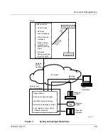
Страница 72: ...ing Syslog services on a router BCC show commands for monitoring Syslog statistics and runtime information Syslog configuration parameters Overview of the Syslog Service You can use the BayRS Syslog messaging service to capture and process router event messages on any UNIX based network management platform The Syslog component of the router software supports this functionality by communicating wit...

Страница 73: ...ards Syslog messages to remote hosts Polls log slot Log slot Router Disk Syslogd daemon Receives syslog messages Identifies message sources Determines message priorities Logs displays prints and or forwards messages Remote Host Unix Workstation Outgoing Syslog messages IP network Message logged Message displayed Message printed Message forwarded UNIX workstation R e t r i e v e s m e s s a g e s P...

Страница 74: ...hich in turn forwards messages to remote hosts identified in the Syslog host table At a remote UNIX management workstation syslogd Receives Syslog messages from Bay Networks routers Examines the priority code in each message Determines the system handling for each message Dispatches each message to any or all of the following destinations Workstation display Local log file Designated printer One o...

Страница 75: ...uter software has a unique entity name Each event message contains the name of the entity that originated logged that message For a complete list of BayRS entity names and their corresponding internal entity numbers refer to the BayRS documentation CD or access the event message database at http support baynetworks com library tpubs events Select by entity number Select by event number range Selec...

Страница 76: ...ntities create a wildcard filter specifying the entity name all Filtering by Event Number Each event message generated by a router entity has a unique number You can create an entity filter that captures only messages that fall within an event number range that you specify using the following filter parameters event lower bound event upper bound Syslog includes the upper and lower boundary values ...

Страница 77: ... severity levels you specify To create this type of filter you must configure a filter name entity name event lower bound 0 event upper bound 255 the wildcard event number severity mask any or all of the following fault warning info trace debug For example if you create an entity filter for FTP with a message severity mask value of warning fault info that filter captures only FTP event messages wi...

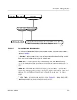
Страница 78: ... 2 to 5 In this case Syslog forwards to the remote host associated with this filter FTP log messages numbered 5 to 27 logged on slots 2 to 5 only You can configure a filter to select messages logged on a specific slot by setting the upper and lower slot boundary values to the same number Mapping Router Event Messages into Syslog Message Format Syslog running on each slot maps filtered event messag...

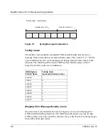
Страница 79: ... in the IP header UDP Data The UDP data field in the Syslog packet contains a reformatted router event message plus a priority code required by the remote host The remote host uses this information to decide how to handle messages received from a router Priority Code A priority code and its text see Figure 10 consist of a facility code plus an error level code in the form facility error Figure 9 S...

Страница 80: ...y names to their respective facility codes on a workstation Mapping Error Message Severity Levels The error level code identifies the level of urgency of a received message for UNIX system handling decisions The following table shows one way to map UNIX system error codes and error levels to the severity levels of event messages from a Bay Networks router UNIX System Facility Name Facility Code eq...

Страница 81: ...he router With time sequencing disabled Syslog forwards event messages to the remote hosts according to the order of slots polled on the router For instructions on how to enable the time sequencing feature see Enabling Sequential Syslog Messaging on page 83 UNIX System Error Codes UNIX System Error Levels Bay Networks Router Event Message Severity Levels 1 LOG_EMERG Fault 2 LOG_ALERT Warning 3 LOG...

Страница 82: ... host you must edit the contents of the etc syslog conf file Configure syslogd on your UNIX workstation as follows 1 Log in as superuser su root 2 Open etc syslog conf and examine the facility level indicators local 0 7 fault warning info trace debug 3 Edit etc syslog conf as needed to achieve message handling appropriate for your management workstation requirements See the examples on page 69 4 S...

Страница 83: ...e display local7 debug TAB dev console local7 info TAB dev console local7 notice TAB dev console local7 err TAB dev console local7 crit TAB dev console local7 alert TAB dev console local7 emerg TAB dev console or local7 debug local7 info local local7 notice local7 err local7 crit local7 alert local7 emerg dev console Messages dispatched to a file local7 info TAB var log syslog file local7 debug TA...

Страница 84: ...om the router 5 Configure entity filters for the new remote host 6 To add more hosts and filters repeat steps 4 and 5 Otherwise continue with step 7 7 Enable system auditing box access audit state enabled 8 Save your new router configuration to a file 9 Exit your BCC session Figure 11 shows the BCC configuration hierarchy for Syslog services on the router Figure 11 BCC Configuration Hierarchy for ...

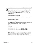
Страница 85: ...face Software To enter BCC configuration mode enter bcc config Reading configuration information please wait done box On AN ANH ARN and BN routers the BCC interface returns the root level prompt box upon entering configuration mode For ASN and System 5000 routers the root level prompt in configuration mode is stack Adding Syslog to the Router Configuration To add Syslog services globally to the ro...

Страница 86: ... host command each time with a new IP address You can point the Syslog service to additional remote hosts up to the value configured for the Syslog maximum hosts parameter To increase or decrease the maximum number of hosts refer to Defining the Maximum Number of Remote Hosts on page 82 Creating an Entity Filter for a Remote Host After you define a remote host you must configure at least one entit...

Страница 87: ...ty parameter The BCC does not have enough information to configure this filter but you get from the list enough information to complete a filter configuration command Filter names must be unique for each host After creating a filter you need to identify the event numbers event severity levels and or slots you want to use as filtering criteria Go to the following sections for that information Filte...

Страница 88: ...event lower bound and event upper bound parameters If you do not want to define filtering by event numbers accept the default values for event lower bound 0 and event upper bound number 255 Then configure the severity levels of events you want to capture for the remote host associated with this filter Accepting the default values for the event lower bound and event upper bound parameters causes Sy...

Страница 89: ...telnet sessions entity telnet filter 192 168 3 4 telnet sessions slot lower bound 3 filter 192 168 3 4 telnet sessions slot upper bound 5 filter 192 168 3 4 telnet sessions Note To specify multiple severity levels other than all concurrently you must enclose these values within braces on the command line and you must insert a space after each value except the last one preceding the closing brace T...

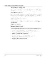
Страница 90: ... config all file vol filename To import into the active configuration a file created by the show config all file command enter source vol filename Managing Syslog Services Once you finish configuring Syslog on a router you may occasionally need to Stop or restart Syslog message forwarding to all remote hosts Stop or restart Syslog message forwarding to a specific remote host Disable or reenable a ...

Страница 91: ...ts navigate to the syslog context and enter enable Example box syslog syslog enable To confirm the change check the current value of the state parameter by entering syslog state state enabled Stopping or Restarting Syslog Messaging to one Host You can stop Syslog messaging to a specific host by disabling that host entry in the router configuration Navigate to the appropriate log host context and e...

Страница 92: ...associated remote host Navigate in configuration mode to the context of the appropriate filter object and enter disable Example box syslog syslog log host 192 168 3 4 log host 192 168 3 4 filter 192 168 3 4 telnet sessions filter 192 168 3 4 telnet sessions disable To confirm the change check the current value of the filter state parameter by entering filter 192 168 3 4 telnet sessions state state...

Страница 93: ...er from a Configured Host To delete an entity filter from a configured host navigate to the appropriate filter context and enter delete Example box syslog syslog log host 192 168 3 4 log host 192 168 3 4 filter 192 168 3 4 telnet sessions filter 192 168 3 4 telnet sessions delete log host 192 168 3 4 Notice that the BCC prompt returns to the configuration context of the remote host associated with...

Страница 94: ... host 192 168 3 4 delete syslog Notice that the BCC prompt returns to the syslog configuration context Deleting a log host automatically deletes all entity filters configured for that host Deleting Syslog Services from the Router To delete all Syslog services from the router navigate to the syslog context and enter delete Example box syslog syslog delete box Notice that the BCC prompt returns to r...

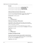
Страница 95: ...outer Enabling sequential Syslog messaging Mapping Router Message Severity Levels to UNIX System Error Levels In most cases you can accept the default mapping between router event severity levels and UNIX system error levels established for a specific filter However you can customize these mappings by entering new values for the following parameters of any Syslog entity filter fault map warning ma...

Страница 96: ...etween Polling Cycles Syslog polls the events log buffer on each slot to retrieve any new messages logged since the previous polling attempt Syslog determines this interval by the value of its log poll timer parameter You can accept the default 5 second interval that Syslog waits to reinitiate a polling cycle across all slots or you can navigate to the syslog context and enter log poll timer secon...

Страница 97: ...ost This feature is disabled by default but you can enable Syslog message sequencing for a specific host To enable Syslog message sequencing navigate to the context of the desired log host object and enter time sequence enabled Example box syslog syslog log host 192 168 125 3 log host 192 168 125 3 time sequence enabled log host 192 168 125 3 Syslog show Commands This section describes how to use ...

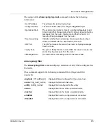
Страница 98: ...cle across all slots Operational State The actual state of the Syslog service up down Active Seq Hosts The number of hosts receiving time sequenced Syslog messages from the router Active Non seq Hosts The number of hosts receiving Syslog messages on a slot by slot basis from the router Messages Sent The total number of Syslog messages forwarded to all remote Syslog hosts configured on this device ...

Страница 99: ...ing Syslog messages from the router Time Sequencing Indicates whether Syslog message time sequencing has been enabled or disabled for the associated remote host UDP Port The UDP port where the remote host receives Syslog messages from the router Facility Code The system facility that the remote UNIX host uses to receive and process Syslog messages from the router Messages Sent The total number of ...

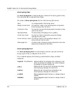
Страница 100: ...fore initiating another cycle to poll all slots for event messages logged since the previous polling cycle maximum hosts Specifies the maximum number of remote hosts you can configure to receive messages from the Syslog service on the router state Specifies the administrative state of the Syslog service on the router enabled or disabled Before the Syslog service can actually begin filtering and fo...

Страница 101: ...wer bound and event upper bound parameters This configures the wildcard event range value of 0 to 255 By accepting the wildcard range Syslog ignores the event lower bound and event upper bound parameters and checks for filtering criteria based only on the value of the severity mask event upper bound Specifies the highest numbered event in the range of events that Syslog will capture and forward to...

Страница 102: ...he range of slots on which Syslog will capture and forward event messages to this filter s host slot upper bound Specifies the highest numbered slot in the range of slots on which Syslog will capture and forward event messages to this filter s host state Specifies the administrative state of this filter enabled or disabled trace map Maps router trace messages to an equivalent host system error lev...

Страница 103: ...ing PROM Boot PROM File Name Boot PROM Revision Number AN ANH andiag exe v7 34 Strata flash feature support anboot exe 9 00 d AN200 an200diag exe v1 00 Strata flash feature support an200boot exe 11 01 ARE BN 5782 MPE arediag pcc v1 16 Strata flash feature support areboot ppc 13 00 ARN arndiag exe v2 16 E7S feature support arnboot exe 1 25 ARN arn diag rom v2 16 E7S feature support Not applicable N...

Страница 104: ......
Отзывы: