background image

4. PACK CONTENTS

The items required for this appliance are packed in two sections.

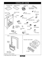
Section 1 - Fire Unit contains:
1 Burner and hotbox unit.
1 Nut & olive for 8mm inlet pipe.
1 Inlet ‘T’ connector and pressure test point.
1 Flue restrictor plate.
2 Screws (For flue restrictor).
2 Screws (For Fireback spacing brackets).
2 Screws (For rear ceramic wall support bracket).
2 Machine screws (For fascia securing)
1 Ceramic back wall.
1  Pair of ceramic side walls.
1 Ceramic fuel effect pack.
2 Small “U” seals for hotbox.
1 Strip of floor sealing tape.
6 Fibre plugs.
4 wood screws.
2 Fire retaining cables.
2 Cable clamps.
4 Eyebolts.
1 Rubber grommet.
1 Smoke match tube.
2 Fireback spacing brackets.
1 Rear ceramic wall support bracket.
1 Length of self adhesive foam seal.
1 Literature pack.
1 Remote control handset.
4 ‘AA’  size batteries for remote receiver.
1 ‘PP3’ size battery for remote handset.

Section 2 - Knightsbridge fascia:
1 Fascia.
1 Firefront casting.
1 Bottom front cover casting.

Carefully remove all the contents. Take special care in handling the ceramic walls and
the ceramic fuel effect pieces. Check that all the listed parts are present and in good
condition.

Page 15

INSTALLER GUIDE

© 

Baxi Heating U.K. Limited 2006.

Содержание 742

Страница 1: ...065 National call rates apply in the United Kingdom In the Republic of Ireland telephone 0044 8706 061 065 INSTALLER Please leave this guide with the owner THIS APPLIANCE IS FOR USE WITH NATURAL GAS G20 WHEN CONVERTED USING CONVERSION KIT NO 0595211 THIS APPLIANCE IS FOR USE WITH PROPANE GAS G31 THIS APPLIANCE IS SUITABLE ONLY FOR INSTALLATION IN THE UNITED KINGDOM GB AND THE REPUBLIC OF IRELAND I...

Страница 2: ...mission to reproduce any part of this publication should be made giving details of the proposed use to the following address The Company Secretary Baxi Heating UK Limited Pentagon House Sir Frank Whittle Road Derby DE21 4XA Warning Any person who does any unauthorised act in relation to a copyright work may be liable to criminal prosecution and civil claims for damages Baxi Fires Division Erdingto...

Страница 3: ...er a BS EN ISO 9001 quality system accepted by the British Standards Institute The Highest Standards Baxi Fires Division is a member of the Society of British Gas Industries which works to ensure high standards of safety quality and performance Careful Installation Baxi Fires Division is a CORGI registered company All our gas fires must be installed by a competent CORGI Registered Installer in acc...

Страница 4: ... Checking the heat settings 26 10 6 To turn the fire back to pilot setting 26 10 7 To turn the fire off 26 10 8 Using the remote control handset 27 10 9 Inlet pressure check 27 11 CERAMIC WALLS INSTALLATION 28 12 FITTING THE FASCIA 28 13 FITTING THE CERAMIC FUEL EFFECT 29 14 FIREFRONT INSTALLATION 29 15 FULL OPERATING CHECKS 29 15 1 Check the control settings 29 15 2 Check for spillage 30 15 3 Fla...

Страница 5: ...ed too heavy then obtain assistance When lifting always keep your back straight Bend your legs and not your back Avoid twisting at the waist It is better to reposition your feet Avoid upper body top heavy bending Do not lean forward or sideways whilst handling the fire Always grip with the palm of the hand Do not use the tips of fingers for support Always keep the fire as close to the body as poss...

Страница 6: ...sequently it is important to take care when handling these articles to ensure that the release of dust is kept to a minimum To ensure that the release of fibres from these RCF articles is kept to a minimum during installation and servicing we recommend that you use a HEPA filtered vacuum to remove any dust and soot accumulated in and around the fire before and after working on the fire When replac...

Страница 7: ...e relevant parts of local regulations All relevant codes of practice The relevant parts of the current editions of the following British Standards BS 715 BS EN 1856 Part 1 BS EN 1858 which replaces BS 1289 Part 1 BS EN 1806 which replaces BS 1289 Part 2 BS EN 1856 Part 1 which replaces BS 4543 Part 2 Page 7 INSTALLER GUIDE Baxi Heating U K Limited 2006 Gas Natural G20 Propane G31 Inlet Pressure 20...

Страница 8: ...rson and also conform to the relevant parts of a The current edition of IS 813 Domestic Gas Installations b All relevant national and local rules in force Where no specific instructions are given reference should be made to the relevant British Standard Code of Practice 3 2 In the United Kingdom as supplied the appliance can be installed in the following situations 3 2 1 To a fireplace complete wi...

Страница 9: ...rement 3 2 2 To a fireplace incorporating a metal flue box complying with the constructional requirements of the current edition of BS715 The dimensions of the flue box must conform to those shown in figure 2 3 2 3 To a precast concrete or clay flue block system conforming to BS1289 or BS EN 1806 with dimensions as in figure 3 The current versions of BS1289 and BS EN 1806 recommend that there shou...

Страница 10: ...s specified in BS715 The liner must be sealed to the surrounding area above the fireplace opening and to the top of the chimney An approved terminal must be fitted A properly constructed precast concrete or clay flue system conforming to BS1289 or BS EN 1806 This system is only suitable if the conditions stated in section 3 2 3 are met 3 4 The flue must conform to BS 5440 Part 1 in design and inst...

Страница 11: ...d to a purpose made proprietary class O 150 C surround The hearth material must be at least 12mm thick The periphery of the hearth or fender should be at least 50mm above floor level to discourage the placing of carpets or rugs over it The surface of the hearth must be sufficiently flat to enable the bottom of the front surround and the bottom front cover to be aligned horizontally Any excessive u...

Страница 12: ...fan may only be used in the same room as this appliance or in any area from which ventilation for the appliance is taken if it does not affect the safe performance of the appliance Note the spillage test requirements detailed further on in this manual If the fan is likely to affect the appliance the appliance must not be installed unless the fan is permanently disconnected 3 15 Normal adventitious...

Страница 13: ...ed brick chimney it is generally unnecessary for the chimney pot to be replaced or for a terminal to be fitted unless the flue has a diameter smaller than 170mm 3 19 The appliance is fitted with an A S D Atmosphere sensing device If the appliance closes down after a period of operation for no apparent reason the consumer should be informed to stop using the appliance until the installation and app...

Страница 14: ... INSTALLER GUIDE Baxi Heating U K Limited 2006 Key A B C D E Model Height mm Width mm Depth into room mm Minimum mandatory clearance to combustible surfaces projecting beyond the front of appliance mm Recommended clearance to non combustible surfaces for access purposes mm knightsbridge 599 492 65 125 10 Figure 5 Appliance dimensions and clearances Dimensions are subject to manufacturing deviation...

Страница 15: ...1 Strip of floor sealing tape 6 Fibre plugs 4 wood screws 2 Fire retaining cables 2 Cable clamps 4 Eyebolts 1 Rubber grommet 1 Smoke match tube 2 Fireback spacing brackets 1 Rear ceramic wall support bracket 1 Length of self adhesive foam seal 1 Literature pack 1 Remote control handset 4 AA size batteries for remote receiver 1 PP3 size battery for remote handset Section 2 Knightsbridge fascia 1 Fa...

Страница 16: ...Page 16 INSTALLER GUIDE Baxi Heating U K Limited 2006 Figure 6 Pack contents ...

Страница 17: ...fascia is used as a template to mark the area for combustible cladding removal and that this area is increased by at least 2mm all round 5 1 3 Soundness for appliance attachment Two primary methods of retaining the appliance are provided 1 By fixing to the fireplace front surround 2 Using concealed tension cables fixed to the rear of the fireplace opening together with secondary fixing to the fire...

Страница 18: ... of escaping smoke indicating a defective flue If there is not a definite flow warm the flue for a few minutes and repeat the smoke pellet test If there is still no definite flow the flue may need remedial work Do not fit the appliance until there is a definite flow through the flue 6 IGNITION CHECK Before attempting to install it is worth checking that the ignition system performs satisfactorily ...

Страница 19: ...ctor at the front The pipe run from the supply line up to the rear opening in the hotbox must be kept away from the area which will be taken by the hotbox when it is installed See figure 7 Note that the centre of the appliance inlet T connector is 25mm above the fireplace floor The inlet T connector should be fitted to the supply pipe at this stage 8 PREPARING APPLIANCE FOR INSTALLATION IMPORTANT ...

Страница 20: ...ack spacer as shown in figure 11 Secure the fireback spacers using the screws removed previously and the two supplied with the fire 6 This appliance is supplied with a flue restrictor for use where the flue draught is excessive The restrictor must NOT be fitted where a precast flue or a flue liner is used For all other installations the restrictor should be fitted There may however be certain exce...

Страница 21: ... foam seal and fit this to the rear of the top flange See figure 13 Cut two 580mm lengths Fit these to the rear outer edges of the side flanges Ensure that there is no gap between the foam seals where they meet at the top flange See figure 13 8 This appliance is supplied with a rear ceramic support bracket Fit this using two screws supplied See figure 14 Page 21 INSTALLER GUIDE Baxi Heating U K Li...

Страница 22: ... in the side flanges of the hotbox See figure 15 4 Remove the hotbox Drill four holes in the fireplace front surround at the marked positions using a no 12 masonry drill 5 Insert a fibre plug into each hole 6 Place the hotbox back in position in the fireplace 7 Fit a wood screw through each hole in the hotbox flanges and tighten to seal the box to the fireplace surround 9 2 Method 2 Cable retentio...

Страница 23: ... Insert one end of each cable one cable each side from the back through the lower of the two holes and return the end through the upper of the holes See figure 17 Give the cables a pull so that they grip against the hotbox flanges 6 Thread the cables through the eyebolts Return the cables through the holes near the bottom of the hotbox back panel See figure 18 For precast or clay block flue system...

Страница 24: ... each cable taut again and push the cable retainers back against the back panel Again tighten the screws in the retainers and apply tension to the cables by turning the hexagonal adjusters clockwise as far as possible 14 Feed the free length of the cables into the gap between the inner and outer back panels so that they are available to allow easy removal and refitting of the appliance during subs...

Страница 25: ...eceiver out of its retention housing See figure 22 Remove the receiver top cover and fit the four AA batteries as indicated inside the receiver base Replace the receiver top cover Slide the receiver back into its housing The ultra sonic sensor must face towards the left of the appliance 2 Fit the PP3 battery to in the remote control handset To do this slide the battery cover back 10 3 Preliminary ...

Страница 26: ...sed the pilot should remain alight If the pilot fails to remain alight repeat the ignition procedure this time keeping the knob depressed for a longer period of time 10 5 Checking the heat settings 1 Once the pilot light is established light the main burner by turning the pilot burner control knob anti clockwise to the main burner on position 3 in figure 23 and by then turning the main burner cont...

Страница 27: ... to the ignition position 2 in figure 23 4 Turn the fire off by rotating the pilot burner control knob to the OFF position 1 in figure 23 10 9 Inlet pressure check The appliance is pre set to give the correct heat input at the inlet pressure shown in section 2 of this guide No adjustment is necessary 1 Check the inlet pressure by fitting a pressure gauge at the test point The test point is on the ...

Страница 28: ...he side walls See figure 27 12 FITTING THE FASCIA 12 1 Fitting the Knightsbridge fascia 1 Carefully lift the fascia Place the fascia against the fireplace front surface so that the two retaining plates at the back of the fascia are directly above the two upper retaining brackets at the top of the hotbox Lower the fascia unit making sure that the retaining plates locate fully into the brackets on t...

Страница 29: ...the screws can be adjusted Lower the firefront casting so that it rests on the hearth See figure 29 2 Hook the front cover casting onto the bottom of the firefront casting 15 FULL OPERATING CHECKS 15 1 Check the control settings With the ceramic fuel effect in position the control operation must now be fully rechecked as in sections 10 4 to 10 8 Make sure that the isolating valve at the T connecto...

Страница 30: ...hat open to the outside of the building closed Recheck for spillage as above If an extractor fan is installed in the same room as the appliance or a connecting room check that spillage does not occur with the fan operating and all doors and other openings between the fan and the appliance open If the smoke is drawn into the appliance continue with the installation If the test is not satisfactory d...

Страница 31: ...ts off the fire the appliance should be switched off and a specialist should be consulted 4 Advise the customer that they should read their owner guide before operating the fire and always follow the advice in the section headed Cleaning your fire Stress that no extra ceramic fuel effect pieces must be added over and above those supplied with the appliance and that any replacements must only be th...

Страница 32: ...d the fire before and after working on the fire When replacing these articles we recommend that the replaced items are not broken up but are sealed within a heavy duty polythene bag clearly labelled as RCF waste RCF waste is classed as a stable non reactive hazardous waste and may be disposed at a landfill licensed to accept such waste Protective clothing is not required when handling these articl...

Страница 33: ...fully lift the fascia upward to clear the upper retaining brackets on the hotbox See figure 32 Pull the fascia clear and place carefully aside 4 Refit in the reverse order Make sure that the fascia is properly located over the upper retaining brackets 17 3 To remove the complete burner unit 1 Remove the lower firefront firefront casting and the fascia See section 17 2 2 Remove the ceramic fuel eff...

Страница 34: ... the reverse order Note 1 The pilot unit is an atmosphere sensing device It must be replaced as a whole assembly Its individual components are not separately replaceable 17 5 To remove the gas valve See figure 37 1 Remove the complete burner module as in section 17 3 2 Remove the electrode lead at the pilot Do this by holding the lead as close to the electrode as possible This will limit the possi...

Страница 35: ...g screw See figure 39 3 Unscrew the injector from the burner 4 Refit in the reverse order 17 8 To remove the appliance from the fireplace 1 Remove the burner unit See section 17 3 2 If the fire retention is as method 1 See section 9 1 of installation instructions remove the screws If the fire retention is as method 2 See section 9 2 of this guide slacken the hexagonal adjusters on the cable retain...

Отзывы: