


3-8
BE1-25A Functional Description
9146600990 Rev M
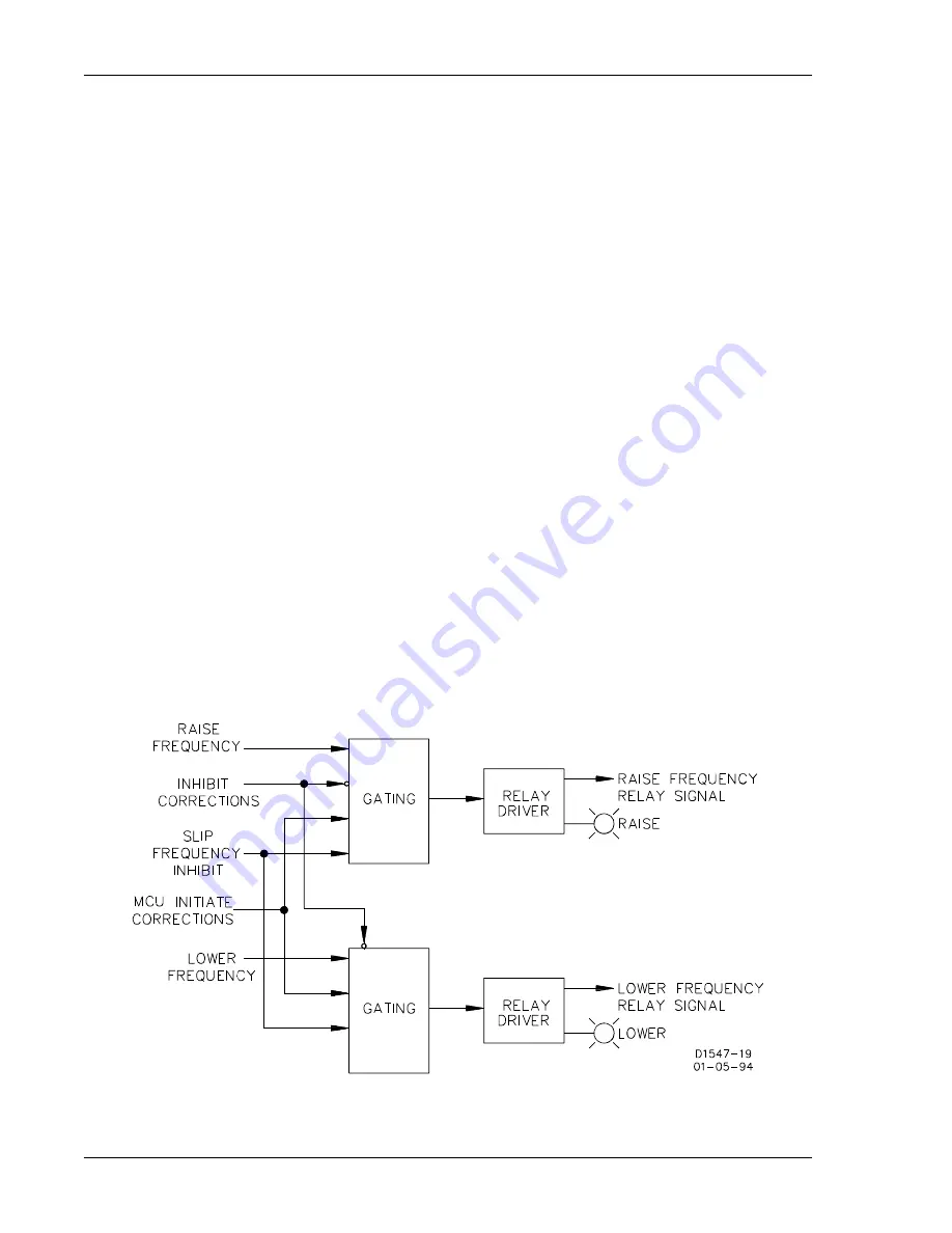
Figure 3-7. Frequency Match (Module F5) Block Diagram
FREQUENCY MATCHING MODULE F5
Frequency Correction
A proportional correction pulse train is issued when the slip frequency is greater than 50 percent of the
maximum slip frequency setting. The pulses are steered (as appropriate) to operate one of the two speed-
adjust output relays. The contacts of one relay are used to signal the generator to raise speed, while the
contacts of the other relay are used to signal the generator to lower the speed. The period of the correction
pulses is determined by the settings loaded into the microprocessor. That is, the period is equal to the sum
of the correction pulse interval plus the correction pulse width. The period remains constant once the
correction pulse width and correction pulse interval are set. The proportional correction pulse is determined
by the percent of correction required. If the slip frequency is greater than four times the maximum slip
allowed, the proportional correction pulse train is at 100 percent of the setting (correction pulse interval
setting plus correction pulse width setting). If the slip frequency is equal to the maximum slip setting, the
proportional correction pulse width is at 25 percent of the original setting. The correction pulse interval (wait
time) will increase to maintain a consistent correction pulse period (total of the pulse interval and pulse
width).
Proportional correction is linear between 100 percent (four times maximum slip frequency setting) and 12.5
percent (equal to one-half maximum slip frequency setting). Synchronization is enabled at slip frequencies
less than the maximum slip setting. Although synchronization is enabled at slip frequencies below 50
percent of the maximum slip allowed, no correction pulses are issued. The pulses issued by this option (to
direct the output relays) may be monitored at the SIG and COM jacks. (+12 Vdc = raise pulse; -12 Vdc =
lower pulse.)
Phase Correction
A target pulse is issued to the correction pulse train when the bus and generator are frequency matched
(within approximately six percent of the maximum slip setting) but not phase matched. The pulses are
steered to induce a slip frequency that may be adjusted to fall within the allowable limits of the correction
pulse train. The contacts of one relay are used to signal the generator to raise speed, while the contacts
of the other relay are used to signal the generator to lower the speed. The frequency of the target pulses
is approximately 1.5 percent of the correction pulse width setting loaded into the microprocessor. The target
pulses issued may be monitored at the SIG and COM jacks and are additional pulses to the correction pulse
train. (+12 Vdc = raise pulse; -12 Vdc = lower pulse.)
www
. ElectricalPartManuals
. com


