


70-4
9424200996
Thermal Curve (49TC) Test
BE1-11
m
capacity (0 - 100%) can be monitored at Metering, Motor, Motor Meter on the front-panel
display. Verify that there is a 49TC target on the front-panel display at Metering > Status >
Targets.
Step 8: Remove three-phase current and wait until thermal capacity falls to 0% before proceeding.
(Note: The thermal capacity is forced to 0% if the 49TC element is disabled and re-enabled.)
Verify that OUT5 (Stopped) closes. Reset all targets.
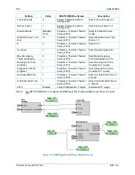
Step 9: Use BESTCOMS
Plus
to open the Thermal Curve (49TC) settings screen. Set the Hot Safe Stall
Time to 1,300 seconds and set the Cold Safe Stall Time to 1,500 seconds. An equivalent
current of 1.8 A is used for the steady state thermal capacity test.
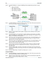
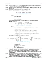
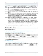
The Steady State Thermal Capacity (TCU) is calculated in Equation 70-4.
𝑇𝑇𝑇𝑇𝑇𝑇
𝑒𝑒𝑒𝑒𝑒𝑒
=
�
𝐼𝐼
𝑒𝑒𝑒𝑒
𝐼𝐼
𝑡𝑡𝑡𝑡𝑡𝑡
�
×
�
1
−
ℎ𝑠𝑠𝑡𝑡
𝑠𝑠𝑠𝑠𝑠𝑠𝑠𝑠
𝑠𝑠𝑡𝑡𝑠𝑠𝑙𝑙𝑙𝑙
𝑡𝑡𝑡𝑡𝑡𝑡𝑠𝑠
𝑠𝑠𝑠𝑠𝑙𝑙𝑠𝑠
𝑠𝑠𝑠𝑠𝑠𝑠𝑠𝑠
𝑠𝑠𝑡𝑡𝑠𝑠𝑙𝑙𝑙𝑙
𝑡𝑡𝑡𝑡𝑡𝑡𝑠𝑠�
=
�
1.8
2
�
×
�
1
−
1300
1500
�
= 0.12 × 100 = 12%
𝑇𝑇𝑇𝑇𝑇𝑇
Equation 70-4. Steady State Thermal Capacity
Where:
I
eq
= Equivalent Thermal Current
I
tpu
= Overload Pickup Current
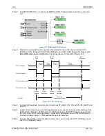
Step 10: Apply 10 Aac three-phase current for five seconds (simulate motor starting). Step three-phase
current down to 1.8 Aac (simulate motor running). Navigate to Metering > Motor > Motor Meter
on the front-panel display and wait until the Thermal Capacity is 12% per Equation 70-4.
Step 11: Step the three-phase current up to 10 Aac (simulate motor starting). Verify that OUT2
(Overloaded) closes indicating an overloaded condition. Measure and record the time from
when current is raised to 10 Aac until OUT1 (Tripped) closes and the thermal capacity reaches
100%. The expected timing is 31.87 seconds (88% of 36.22 seconds because %TC starts at
12%). Reference Equation 70-3. The thermal capacity (12 to 100%) can be monitored at
Metering > Motor > Motor Meter on the front-panel display. Verify that there is a 49TC target on
the front-panel display at Metering > Status > Targets.
Step 12: Remove three-phase current and wait until thermal capacity falls to 0% before proceeding.
Verify that OUT5 (Stopped) closes. Reset all targets.
Step 13: Use BESTCOMS
Plus
to open the Thermal Curve (49TC) settings screen. Set the Max
Emergency Thermal Capacity to 200%.
Step 14: Momentarily close IN1 to enable an emergency start. An emergency start expires after one
minute if current is not applied. OUT3 toggles when Input 1 is closed. Apply 10 Aac three-phase
current (simulate motor starting). Verify that OUT2 (Overloaded) closes indicating an
overloaded condition. Verify that OUT4 (Starting) closes. Measure and record the time from
when current is applied until OUT1 (Tripped) closes and the thermal capacity reaches 200%.
The expected timing is 72.44 seconds per Equation 70-3 multiplied by 2 since the 49TC is set to
trip at 200% thermal capacity. The thermal capacity (0 to 200%) can be monitored at Metering >
Motor > Motor Meter on the front-panel display. Verify that there is a 49TC target on the front-
panel display at Metering > Status > Targets.
Step 15: Remove three-phase current and wait until thermal capacity falls to 0% before proceeding.
(Note: The thermal capacity is forced to 0% if the 49TC element is disabled and re-enabled.)
Verify that OUT5 (Stopped) closes. Reset all targets.
RTD Biasing (Optional)
If the RTD Biasing test will not be performed, skip to User Curve (Step 25).
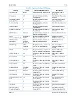
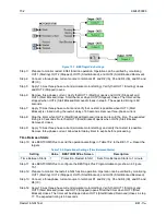
Step 16: Use BESTCOMS
Plus
to send the operational settings in Table 70-2 to the BE1-11
m
. Reset all
targets.
Содержание BE1-11m
Страница 8: ...vi 9424200996 Revision History BE1 11m...
Страница 12: ...x 9424200996 Contents BE1 11m...
Страница 21: ...9424200996 1 9 BE1 11m Introduction Figure 1 1 Style Chart...
Страница 22: ...1 10 9424200996 Introduction BE1 11m...
Страница 40: ...3 6 9424200996 Controls and Indicators BE1 11m Figure 3 3 Front Panel Display Setup Screen...
Страница 53: ...9424200996 5 5 BE1 11m Phase Undervoltage 27P Protection Figure 5 3 Phase Undervoltage Settings Screen...
Страница 54: ...5 6 9424200996 Phase Undervoltage 27P Protection BE1 11m...
Страница 56: ...6 2 9424200996 Negative Sequence Voltage 47 Protection BE1 11m...
Страница 61: ...9424200996 7 5 BE1 11m Phase Overvoltage 59P Protection Figure 7 3 Overvoltage Settings Screen...
Страница 62: ...7 6 9424200996 Phase Overvoltage 59P Protection BE1 11m...
Страница 68: ...8 6 9424200996 Auxiliary Overvoltage 59X Protection BE1 11m...
Страница 80: ...12 4 9424200996 Instantaneous Overcurrent 50 Protection BE1 11m...
Страница 84: ...13 4 9424200996 Breaker Failure 50BF Protection BE1 11m...
Страница 91: ...9424200996 14 7 BE1 11m Inverse Overcurrent 51 Protection Figure 14 4 Inverse Overcurrent Settings Screen...
Страница 92: ...14 8 9424200996 Inverse Overcurrent 51 Protection BE1 11m...
Страница 105: ...9424200996 18 3 BE1 11m Power Factor 55 Protection Figure 18 2 Power Factor Settings Screen...
Страница 106: ...18 4 9424200996 Power Factor 55 Protection BE1 11m...
Страница 110: ...19 4 9424200996 Resistance Temperature Detector 49RTD Protection BE1 11m...
Страница 118: ...20 8 9424200996 Thermal Curve 49TC Protection BE1 11m...
Страница 122: ...22 2 9424200996 Starts per Time Interval 66 Protection BE1 11m...
Страница 124: ...23 2 9424200996 Restart Inhibit Protection BE1 11m...
Страница 130: ...25 4 9424200996 Virtual Control Switches 43 BE1 11m Figure 25 3 Virtual Control Switches Settings Screen...
Страница 140: ...28 4 9424200996 Breaker Control Switch 101 BE1 11m...
Страница 148: ...29 8 9424200996 Setting Groups BE1 11m...
Страница 156: ...30 8 9424200996 Metering BE1 11m Figure 30 11 RTD Meter Screen...
Страница 158: ...31 2 9424200996 Digital Points BE1 11m Figure 31 2 Digital Points Monitor Screen...
Страница 177: ...9424200996 34 5 BE1 11m Motor Reporting Figure 34 9 Learned Motor Data Screen...
Страница 178: ...34 6 9424200996 Motor Reporting BE1 11m...
Страница 184: ...35 6 9424200996 Alarms BE1 11m...
Страница 186: ...36 2 9424200996 Differential Reporting BE1 11m...
Страница 196: ...38 4 9424200996 Demands BE1 11m...
Страница 198: ...39 2 9424200996 Load Profile BE1 11m...
Страница 207: ...9424200996 41 5 BE1 11m Trip Circuit Monitor 52TCM Figure 41 6 Trip Circuit Monitor Settings Screen...
Страница 208: ...41 6 9424200996 Trip Circuit Monitor 52TCM BE1 11m...
Страница 212: ...42 4 9424200996 Fuse Loss 60FL BE1 11m...
Страница 218: ...43 6 9424200996 BESTnet Plus BE1 11m Figure 43 8 Power Quality Page...
Страница 221: ...9424200996 44 3 BE1 11m Mounting Figure 44 3 Case Side Dimensions...
Страница 227: ...9424200996 44 9 BE1 11m Mounting Figure 44 9 Retrofit Mounting Plate Basler P N 9424200073 Part 2...
Страница 235: ...9424200996 45 5 BE1 11m Terminals and Connectors Figure 45 7 Example of Reversed CT Polarity...
Страница 236: ...45 6 9424200996 Terminals and Connectors BE1 11m...
Страница 269: ...9424200996 48 15 BE1 11m BESTlogic Plus Figure 48 4 Logic Page 1 for Default Logic...
Страница 288: ...49 10 9424200996 Communication BE1 11m Figure 49 14 Modbus Mapping Screen...
Страница 301: ...9424200996 51 5 BE1 11m Timekeeping Figure 51 3 Front Panel Circuit Board Backup Battery Location...
Страница 306: ...52 4 9424200996 Device Information BE1 11m...
Страница 314: ...53 8 9424200996 Configuration BE1 11m Figure 53 3 Display Units Screen...
Страница 318: ...54 4 9424200996 Introduction to Testing BE1 11m...
Страница 330: ...56 6 9424200996 Commissioning Testing BE1 11m...
Страница 336: ...58 4 9424200996 Phase Undervoltage 27P Test BE1 11m...
Страница 340: ...59 4 9424200996 Phase Overvoltage 59P Test BE1 11m...
Страница 352: ...60 12 9424200996 Auxiliary Overvoltage 59X Test BE1 11m...
Страница 360: ...61 8 9424200996 Frequency 81 Test BE1 11m...
Страница 364: ...62 4 9424200996 Instantaneous Undercurrent 37 Test BE1 11m...
Страница 376: ...63 12 9424200996 Instantaneous Overcurrent 50 Test BE1 11m...
Страница 396: ...65 16 9424200996 Inverse Overcurrent 51 Test BE1 11m...
Страница 408: ...67 6 9424200996 Power 32 Test BE1 11m...
Страница 412: ...68 4 9424200996 Loss of Excitation Reverse Var Based 40Q Test BE1 11m...
Страница 426: ...70 10 9424200996 Thermal Curve 49TC Test BE1 11m...
Страница 432: ...72 4 9424200996 Starts per Time Interval 66 Test BE1 11m...
Страница 436: ...73 4 9424200996 Restart Inhibit Test BE1 11m...
Страница 440: ...74 4 9424200996 Virtual Control Switches 43 Test BE1 11m...
Страница 450: ...75 10 9424200996 Logic Timers 62 Test BE1 11m...
Страница 464: ...79 8 9424200996 Troubleshooting BE1 11m...
Страница 480: ...80 16 9424200996 Specifications BE1 11m...
Страница 496: ...82 8 9424200996 Time Curve Characteristics BE1 11m Figure 82 3 Time Characteristic Curve A Standard Inverse BS 142...
Страница 497: ...9424200996 82 9 BE1 11m Time Curve Characteristics Figure 82 4 Time Characteristic Curve A1 Inverse IEC 60255 151 Ed 1...
Страница 504: ...82 16 9424200996 Time Curve Characteristics BE1 11m Figure 82 11 Time Characteristic Curve G Long Time Inverse BS 142...
Страница 507: ...9424200996 82 19 BE1 11m Time Curve Characteristics Figure 82 14 Time Characteristic Curve B Very Inverse BS 142...
Страница 512: ...82 24 9424200996 Time Curve Characteristics BE1 11m Figure 82 19 Time Characteristic Curve C Extremely Inverse BS 142...
Страница 570: ...84 26 9424200996 Settings Calculation Examples BE1 11m Figure 84 31 Time vs Current and Thermal Limit Curves...
Страница 597: ...9424200996 84 53 BE1 11m Settings Calculation Examples Figure 84 67 Logic Page 1 Unchanged from Induction Motor Default...
Страница 598: ...84 54 9424200996 Settings Calculation Examples BE1 11m Figure 84 68 Logic Page 2 Unbalance Trip and Alarm Added...
Страница 599: ...9424200996 84 55 BE1 11m Settings Calculation Examples Figure 84 69 Logic Page 3 Power Factor 55 Added...
Страница 600: ...84 56 9424200996 Settings Calculation Examples BE1 11m Figure 84 70 Logic Page 4 Part 1...
Страница 602: ...84 58 9424200996 Settings Calculation Examples BE1 11m...
Страница 608: ...85 6 9424200996 BESTCOMSPlus Settings Loader Tool BE1 11m...
Страница 609: ......