Jacks
3
Either 1/4" or 1/8"
Knobs
5
The Board
The PCB is 100mm x 41mm. The pots are spaced 21mm apart. The mounting holes are spaced
91mm x 29mm.
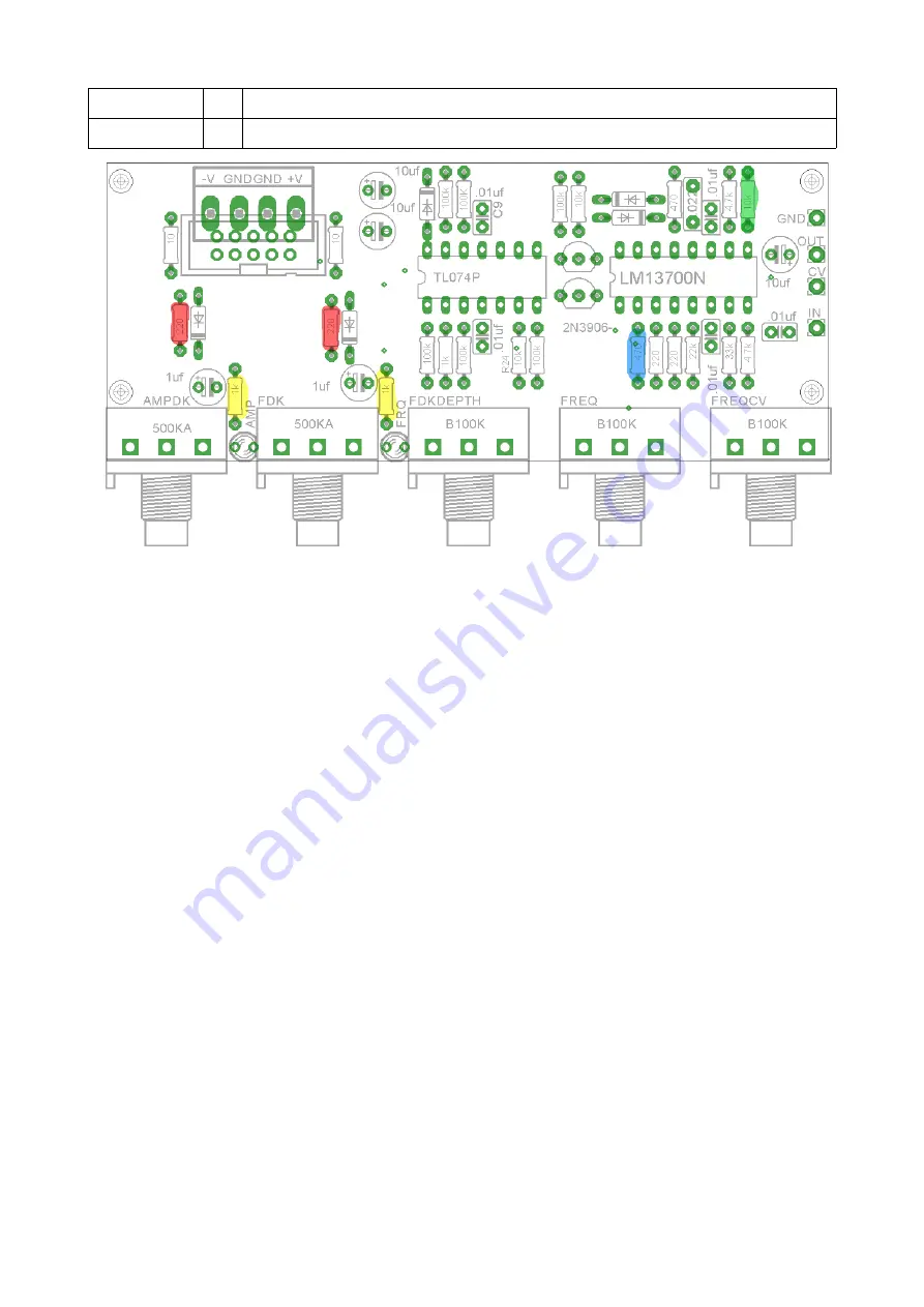
I've highlighted a few key resistors that a builder may want to modify.
The yellow resistors control the brightness of the LEDs. 1K is appropriate for normal Red, Green
or Yellow LEDs. For high effeciency LEDs of these colors or blue/white LEDs try changing to
10K.
The red resistors control the minimum decay time. To increase the minimum time, increase the
value of the resistor. If you have a problem where when turning one of the decay pot times down
all the way where the decay controlled by the other pot is also shortened, you should increase the
value of these resistors.
The blue resistor controls the minimum frequency on the frequency control pot. Increase it to
increase the minimum frequency.
The green resistor is the 10K that should be replaced with a 15K for +/-15V
WIRING
The PCB has four wirepads, they should be connected as follows:
IN → Tip of the Trigger/Gate Input Jack
CV → Tip of the CV Input Jack
OUT → Tip of the Output jack, and optionally the switch of the CV jack.
GND → The sleeve of any one jack if using a metal panel. If using a non-conductive panel, then
connect the sleeves of the jacks together.
Содержание BMC018.Analog Drum
Страница 3: ......


