background image

3

Important Information

This manual contains important operating and
safety information. You must carefully read and
understand the contents of this manual prior to
the use of this equipment.

Your Thermolyne FB1300 Model or FB1400
Model Furnace has been designed with function,
reliability, and safety in mind. It is your responsi-
bility to install it in conformance with local elec-
trical codes. For safe operation, please pay
attention to the alert signals throughout the man-
ual.

Warnings

To avoid electrical shock, this furnace must:

1.

Use a properly grounded electrical outlet
of correct voltage and current handling
capacity.

2.

Be disconnected from the power supply
before servicing.

3.

Have the door switch operating properly.

To avoid burns:

1.

“Caution: Hot Surface. Avoid Contact.”
Do not touch the exterior or interior sur-
faces of the furnace during use or for a
period of time after use.

To avoid personal injury:

1.

Do not use in the presence of flammable
or combustible materials — fire or explo-
sion may result. This device contains
components which may ignite such
material.

2.

Refer servicing to qualified personnel.

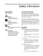
Safety Information

Warning
Warnings alert you to a 
possibility of personal injury.

Caution
Cautions alert you to a 
possibility of damage to the
equipment.

Note
Notes alert you to pertinent facts
and conditions.

Hot Surface
Hot surfaces alert you to a 
possibility of personal injury if
you come in contact with a 
surface during use or for a 
period of time after use.

Alert Signals

Содержание FB1300

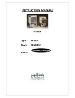
Страница 1: ...INSTRUCTION MANUAL Furnace Type FB1400 Model FB1410 M Brand...

Страница 2: ...TEAD THERMOLYNE CORPORATION Type FB1300 FB1400 Furnaces OPERATION AND REPAIR MANUAL AND PARTS LIST SERIES 1049 1050 Model Numbers FB1310M FB1310M 26 FB1314M FB1315M FB1318M FB1310M 33 FB1410M FB1410M...

Страница 3: ...Switches 10 Digital Readout 10 Push To Set Temperature Button 11 Temperature Adjustment Knob 11 Digital Control 11 Sensor Break Protection 12 Furnace Loading 13 Preventive Maintenance 14 Troubleshoot...

Страница 4: ...rom the power supply before servicing 3 Have the door switch operating properly To avoid burns 1 Caution Hot Surface Avoid Contact Do not touch the exterior or interior sur faces of the furnace during...

Страница 5: ...rials can be located in the door the hearth collar in the chamber of the product or under the hot plate top Tests performed by the manufacturer indicate that there is no risk of exposure to dust or re...

Страница 6: ...e overall shape and general features of the unit General Usage Do not use this product for anything other than its intended usage Principles of Operation The furnace chamber is heated by a single thre...

Страница 7: ...ollution Degree 2 in accordance with IEC 664 Altitude limit 2 000 meters Storage 25 C 65 C 20 80 relative humidity FB1400 Models Dimensions handle not included Chamber 5 W x 4 25 H x 6 D 13 x 11 x 15...

Страница 8: ...Part I General Requirements EN 1010 2 010 Part II Particular requirements for laboratory equipment for the heating of materials per the provisions of the Electromagnetic Compatibility Directive 89 33...

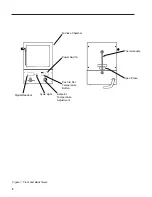
Страница 9: ...8 Figure 1 Front and Back Views Thermocouple Spec Plate Furnace Chamber Power Switch Push to Set Temperature Button Setpoint Temperature Adjustment Cycle Light Digital Readout...

Страница 10: ...specifications are located on the specification plate on the back of the fur nace Consult Barnstead Thermolyne if your electrical service is different than those listed on the specification plate Prio...

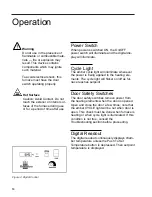
Страница 11: ...check must be done when furnace is heating or when cycle light is illuminated If this condition is not true consult the Troubleshooting section before proceeding Digital Readout The digital readout co...

Страница 12: ...utton turn the tempera ture knob until you reach the desired setpoint temperature as indicated on digital display 3 Release the Push To Set Temperature button The digital display will now indicate the...

Страница 13: ...es sensor break protec tion in the event the thermocouple opens If an open thermocouple condition occurs the digital display will indicate 5 degrees or less and the power to the heating element will b...

Страница 14: ...se your load up off the furnace floor with small pieces of ceramic or a hearth plate to promote even heating Use insulated tongs and mittens when loading and unloading furnace Always wear safety glass...

Страница 15: ...nace up to 871 C 1600 F empty occasionally to burn off the conta mination that may exist on the insulation and ele ments Run for approximately two hours with the door slightly open Element life is red...

Страница 16: ...t Install proper element Repeated element burnout Overheating furnace Keep furnace under maximum temperature Heating harmful materials Enclose material in container Clean up spills in and on chamber V...

Страница 17: ...ator 3 When the thermocouple tip is clear of the furnace back bend it out of the way 4 Remove the screws holding the steel back plate to the case 5 Remove the steel back plate Thermocouple Cover Warni...

Страница 18: ...be reused if it has not been contaminated 9 Remove the old element lead wire and power wires from the terminal block and save the glass sleeving for re installation on the new element leads Sleeving m...

Страница 19: ...ey lie close to the refractory plate and the bottom insulation block The easiest and safest way to do this is to press the wire flat with a stick or blunt pusher Do not use a sharp object or nick the...

Страница 20: ...1 Replace thermocouple cover 22 If replacement of back insulation is necessary carefully redrill hole for thermocouple using back cover as guide 23 Reconnect furnace to power supply 24 Test operation...

Страница 21: ...ock 10 Secure the two yellow wires marked together on the terminal block Secure the two red wires together on the adjacent terminal Make sure connec tions are secure to terminal block A polarity test...

Страница 22: ...furnace chamber 8 Remove screws from door switch bracket 9 Remove the control section from the furnace chamber Remove plates Be sure to note how plates are secured together for reassembly 10 Remove ba...

Страница 23: ...of insula tion over hearth plate Element leads and ceramic bushings should be exposed above insulation bottom piece 18 Thread the element leads and ceramic bushings through the bottom plate Bend the l...

Страница 24: ...Reconnect the wires to new door switches 6 Replace bottom cover and turn furnace upright 7 Reconnect furnace to power supply 8 Test operation of door switches as described in step d To Replace Solid...

Страница 25: ...isconnect wires from PC Board Identify or mark wires disconnected to ensure proper placement and connec tion when re installing 3 Remove PC Board from bottom cover 4 Install new PC Board and secure 5...

Страница 26: ...R1 Resistor Pot RY1 Relay Solid State S1 Switch Power S2 Switch Door S3 Switch Door S4 Switch Setpoint TB1 Terminal Block TB2 Terminal Block TC TC1 Thermocouple J6 S4 R1 CN1 GND J3 J1 HI AC J2 J5 LOW...

Страница 27: ...26 Exploded View...

Страница 28: ...s 1 JC48X1 8 Insulation Top all FB1300 1 JC44X3 8 Insulation Top all FB1400 1 JC48X3 9 Insulation Hearth Collar FB1300 1 HC44X1 9 Insulation Hearth Collar FB1400 1 HC48X1 10 Insulation Sides FB1300 2...

Страница 29: ...d this unit or can be obtained promptly from the factory When service or replacement parts are needed we ask that you check first with your dealer If the dealer cannot handle your request then contact...

Страница 30: ...own discre tion Heating elements however because of their susceptibility to overheating and conta mination must be returned to our factory and if upon inspection it is concluded that fail ure is not d...

Страница 31: ...30...

Страница 32: ...31...

Страница 33: ...9001 ISO REGISTERED Barnstead Thermolyne 2555 Kerper Blvd P O Box 797 Dubuque IA 52004 2241 Phone 319 556 2241 800 553 0039 Fax 319 589 0516 E Mail Address mkt barnstead com...

Отзывы: