Manual 2100-443Page 10
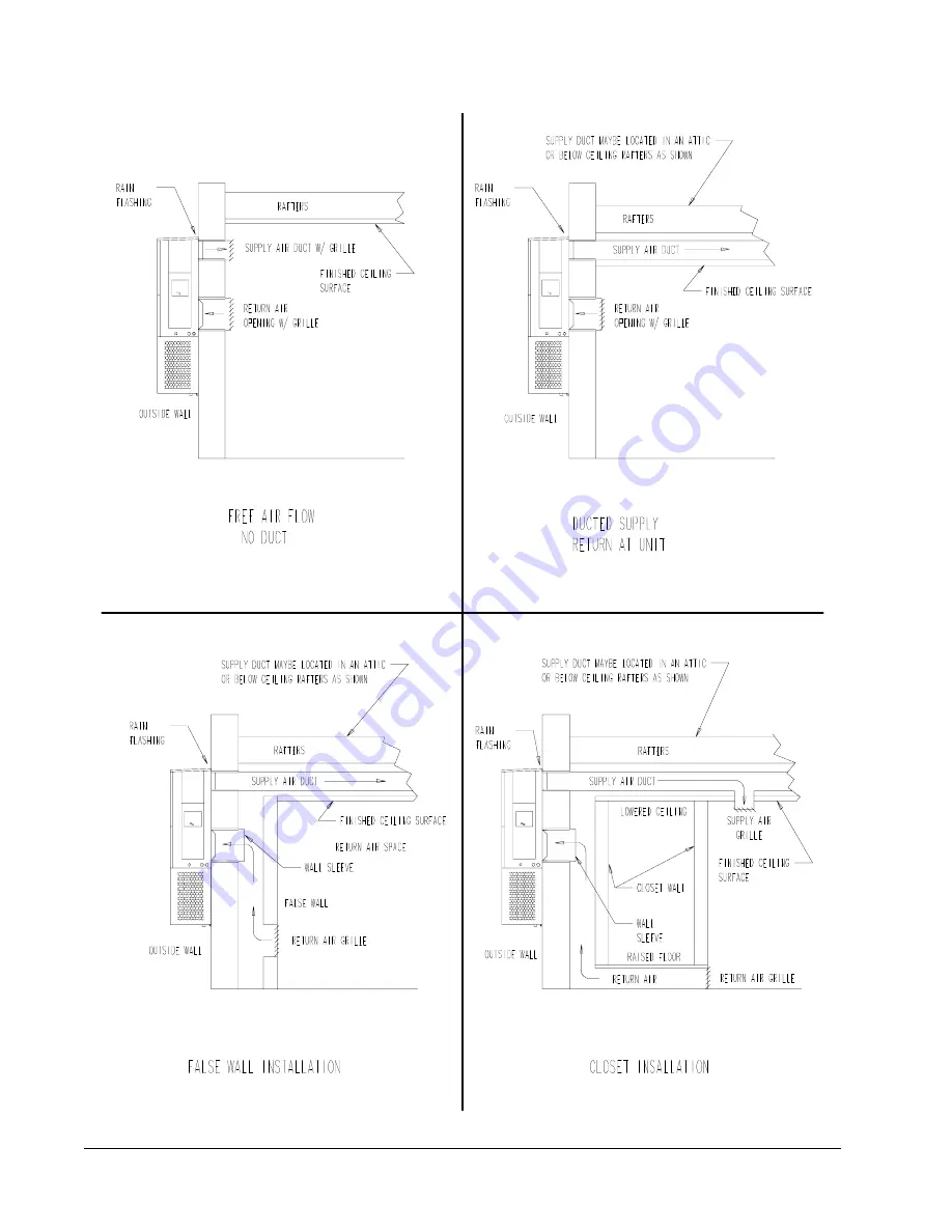
FIGURE 7
COMMON WALL-MOUNTING INSTALLATIONS
MIS-550
Страница 1: ...T PUMPS MODELS WH422D WH484D WH603D INSTALLATION INSTRUCTIONS Copyright 2003 Manual 2100 443 Supersedes File Volume III Tab 17 Date 10 23 03 Bard Manufacturing Company Bryan Ohio 43506 Since 1914 Movi...
Страница 2: ...or 19 Fan Blade Dimensions 20 Removal of Fan Shroud 20 Refrigerant Charge 20 Pressure Tables 21 22 Optional Accessories 23 Figures Figure 1 Unit Dimensions 3 Figure 2 Blower Damper Assembly 6 Figure 3...
Страница 3: ...tems Load Calculation for ACCA Manual J or N Residential Winter and Summer Air Conditioning Low Pressure Low Velocity ACCA Manual D or Q Duct System Design for Winter and Summer Air Conditioning For m...
Страница 4: ...3 0 0 6 5 2 CONTROL MODULES NOTE For 0 KW and circuit breakers 230 208 V or pull disconnects 460 V applications insert 0Z in the KW field of model number MODEL NUMBER CAPACITY 42 3 1 2 Ton 48 4 Ton 6...
Страница 5: ...Manual 2100 443 Page 3 FIGURE 1 UNITDIMENSIONS MIS 411...
Страница 6: ...1 4 3 0 6 6 8 0 5 0 7 0 9 8 6 3 0 1 8 8 A N 4 3 4 3 A N 6 2 2 5 A N 0 5 0 5 A N 0 3 0 6 A N 8 8 A N 0 1 6 A N 0 1 0 1 A N 0 1 0 1 Z 0 B 0 0 B D 2 2 4 H W 6 0 B 3 9 0 B 3 8 0 2 0 3 2 1 1 1 6 2 4 4 3 5...
Страница 7: ...rs of America ACCA is an excellent guide to proper sizing All duct work or portions thereof not in the conditioned space should be properly insulated in order to both conserve energy and prevent conde...
Страница 8: ...er drainage FRESH AIR INTAKE All units are built with fresh air inlet slots punched in the service panel If the unit is equipped with the fresh air damper assembly the assembly is shipped already atta...
Страница 9: ...pening would then be 32 x 12 See Figures 2 4 and 7 for details 3 Locate and mark lag bolt locations and bottom mounting bracket location See Figure 4 4 Mount bottom mounting bracket 5 Hook top rain fl...
Страница 10: ...required from combustible materials Supply Air Duct Return Air Opening Wall Circuit breaker access door Heater access panel Note It is recommended that a bead of silicone caulking be placed behind the...
Страница 11: ...3 Page 9 FIGURE 5 WALL MOUNTINGINSTRUCTIONS FIGURE 6 WALL MOUNTINGINSTRUCTIONS MIS 548 MIS 549 SEE FIGURE 3 MOUNTING INSTRUCTIONS SEE UNIT DIMENSIONS FIGURE 1 FOR ACTUAL DIMENSIONS SEE FIGURE 1 FOR DU...
Страница 12: ...Manual 2100 443 Page 10 FIGURE 7 COMMONWALL MOUNTINGINSTALLATIONS MIS 550...
Страница 13: ...WIRING 230 208V 1 phase and 3 phase equipment dual primary voltage transformers All equipment leaves the factory wired on 240V tap For 208V operation reconnect from 240V to 208V tap The acceptable ope...
Страница 14: ...ENERGY MONITOR FULL TIME DEHUMIDIFICATION IMPORTANT NOTE Only the thermostat and subbase combinations as shown in Table 4 will work with this equipment The thermostat and subbase must be matched and t...
Страница 15: ...MMABLETHERMOSTATFULLTIMEDEHUMIDIFICATION IMPORTANT NOTE Only the thermostat and subbase combinations as shown in Table 4 will work with this equipment The thermostat and subbase must be matched and th...
Страница 16: ...tc that will prevent compressor from operating will cause red lamp to activate This is a signal to the operator of the equipment to place system in emergency heat position TABLE 3 THERMOSTATWIRESIZE r...
Страница 17: ...nitor on page 15 of this manual Verification of proper rotation must be made any time a compressor is change or rewired If improper rotation is corrected at this time there will be no negative impact...
Страница 18: ...irculation HEATING SEQUENCE On a call for heating the compressor and reversing valve of the unit are energized to provide heat pump heating If the room temperature falls below the 2nd stage heating se...
Страница 19: ...ver or other metallic object or another 1 4 inch QC to short between the SPEEDUP terminals to accelerate the HPC timer and initiate defrost Be careful not to touch any other terminals with the instrum...
Страница 20: ...l p e R t o n g n i s a h p r e w o P t c e r r o c e s a h p n o D E L d e r r o f k c e h C y l n o s t i n u e s a h p 3 r o t i n o m t i n u e h t o t s d a e l r e w o p o w t h c t i w S r o t...
Страница 21: ...85371 82699 80121 77632 75230 72910 70670 68507 66418 64399 62449 60565 58745 56985 55284 53640 52051 50514 49028 47590 46200 44855 43554 42295 41077 25 0 26 0 27 0 28 0 29 0 30 0 31 0 32 0 33 0 34 0...
Страница 22: ...8 4 H W 3 0 6 H W 5 7 1 TABLE 9 INDOORBLOWERPERFORMANCE CFM 230V P S E H n i 2 O 4 8 4 H W 2 2 4 H W 3 0 6 H W V 0 3 2 w o L V 0 3 2 h g i H V 0 3 2 w o L V 0 3 2 h g i H l i o C y r D l i o C t e W l...
Страница 23: ...7 5 0 2 5 7 0 2 2 7 7 5 3 2 8 7 1 5 2 9 7 6 6 2 0 8 2 8 2 0 8 7 9 2 1 8 3 1 3 2 8 9 2 3 B D g e d 0 8 B W g e d 7 6 e d i S w o L e d i S h g i H 9 7 0 1 2 0 8 6 2 2 2 8 1 4 2 3 8 7 5 2 4 8 3 7 2 5 8...
Страница 24: ...ription 5 0 A 2 4 H W H E s e g a k c a P r e t a e H X 0 1 A 2 4 H W H E s e g a k c a P r e t a e H X 6 0 C 2 4 H W H E s e g a k c a P r e t a e H X 5 0 A 4 0 H W H E s e g a k c a P r e t a e H X...
Страница 25: ...t a e H e g a t S t s 1 d e i p u c c O X X X X X X g n i t a e H e g a t S t s 1 m u h e D w X X X X X X X X X g n i t a e H e g a t S d n 2 d e i p u c c o n U X X X X X X X X X g n i t a e H e g a...