Bard WG3S2-A Скачать руководство пользователя страница 56

Manual 2100-587C

Page 

56 of 59

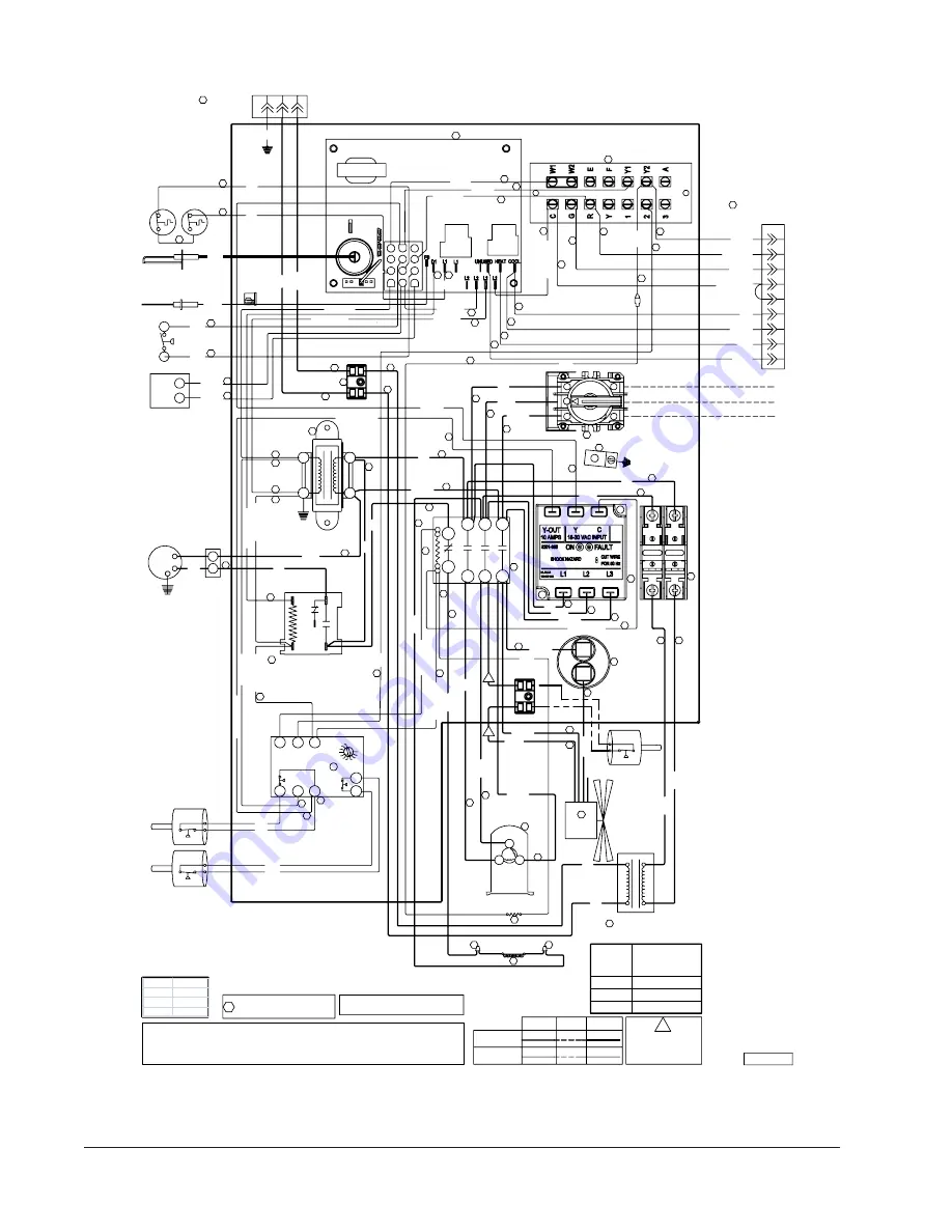
WG3S2-C, WG4S2-C, WG5S2-C     460/60/3

T2

NC

C

L2 L3

Au

x.

L1

T1

T3

LP

C

CC

HP

C

Y

AL

R

C

LP

C

M

IN

UT

ES

4

2

3

5

R

1

46

0V

23

0V

PINK

PI

NK

BLUE

BLUE

BLUE

5

4

3

GR

BLUE

BLUE

1 2 3

4 5 6

8 9

7

12

10 11

BLUE

BLUE

PURPLE

PURPLE

PURPLE

C

MV

NO

MV

YELLOW

ORANGE

YELLOW

YELLOW

RE

D

YE

LL

OW

/B

LA

CK

BR

OW

N/

W

HI

TE

YE

LL

OW

/R

ED

YELLOW

YELLOW

YELLOW

YELLOW

L2

L1

YELLOW/BLACK

YELLOW

42

RED

RE

D

RE

D

RE

D/

W

HI

TE

RED/WHITE

RED

RE

D

RED

RED

4

TERM. BLOCK

62

RED/WHITE

49

49

45

53

RED

RED

RED

43

RED

RE

D

High Voltage

Factory

Optional

38

Field

Wire Identification numbers

for Bard use only.

99

Low Voltage

44

RED

1

3

2

6

A

57

RED/

WHITE

RED/WHITE

32

A

RED

32

47

RED

(OPT.)

BLACK

BL

AC

K

BLACK

BL

AC

K

16 PIN PLUG FOR

INDOOR BLOWER

MOTOR

BL

AC

K

TRANSFORMER

SPEED

15

0

13

5

12

0

FUSE

FOR INDOOR

BLOWER MOTOR

13

2

6

10

1

3

15

12

14

BL

AC

K/

W

HI

TE

PIN PLUG

460-60-3

BROWN

BL

AC

K

BLACK

P3

BLACK/WHITE

STEP DOWN

1

PL

1

2

BR

GRAY

BLACK/WHITE

BLACK

BR

OW

N

BL

AC

K/

W

HI

TE

BL

AC

K

BLACK

BROWN

BL

AC

K/

W

HI

TE

BL

AC

K

BLACK/WHITE

BL

AC

K/

W

HT

IE

BLACK/WHTIE

SOLENOID

BLACK/WHITE

BLACK

27

USE COPPER CONDUCTORS

SUITABLE FOR AT LEAST 75° C

TERM. BLOCK

GR

AY

IF ANY ORIGINAL WIRE AS SUPPLIED WITH THE APPLIANCE MUST BE

REPLACED, IT MUST BE REPLACED WITH WIRING MATERIAL HAVING A

TEMPERATURE RATING OF AT LEAST 105° C EXCEPT THE IGNITION CABLE

WHICH IS 250°C HIGH VOLTAGE CABLE

OUTDOOR

FAN

MOTOR

INTEGRATED FURNACE CONTROL

13

11

LOW

VOLTAGE

STRIP

28

DISCONNECT

21

TRANSFORMER

18

GROUND TERMINAL

25

PH

AS

E

M

ON

IT

OR

19

INDUCED DRAFT

BLOWER RELAY

23

CAPACITOR

LOW

PRESSURE

SWITCH

HIGH

PRESSURE

SWITCH

16

COMPRESSOR

CONTROL

MODULE

460V

COM

R

C

CO

M

PR

ES

SO

R

CO

NT

AC

TO

R

CRANKCASE

HEATER

HIGH SPEED

50

Compressor

51

INDUCED

DRAFT BLOWER

GAS

VALVE

20

32

52

37

35

35

40

40

35

35

32

32

32

32

32

32

34

32

62

28

28

28

37

28

27

27

41

38

36

47

41

28

28

28

38

39

PRIMARY

LIMIT

FLAME

ROLLOUT

SPARK IGNITOR

FLAME SENSOR

PRESSURE

SWITCH

32

28

35

51

51

51

46

46

46

48

47

T3

T1

T2

YELLOW

31

30

29

L3

52

32

15

32

4085-377 A

59

59

59

59

59

54

FU

SE

BL

OC

K

55

56

60

60

32

32

LOW AMBIENT

CONTROL (OPT.)

A

WIRES CONNECT

IF OPTION

NOT USED

MODEL

STEPDOWN

TRANSFORMER

CLASS CC FUSE

WG3S

5 A

WG4S

7 A

WG5S

7 A

33

Model Capacitor

WG3S2-C

15/370

WG4S2-C

15/370

WG5S2-C

15/370

Содержание WG3S2-A

Страница 1: ...B WG5S2 B WG3S2 C WG4S2 C WG5S2 C WARNING READ ALL INSTRUCTIONS CAREFULLY BEFORE BEGINNING THE INSTALLATION THE INSTALLATION MUST COMPLY WITH THESE INSTRUCTIONS AND THE REQUIREMENTS OF ALL GOVERNING...

Страница 2: ...21 Standard Orifice Sizing High Altitude Derate 29 22 Conversion of Gas Input BTUH From High to Low Rating 31 23 Measuring Air Temperature Rise 31 24 Filters 32 25 Compressor Control Module 32 33 26 L...

Страница 3: ...6 Figure 13 Access Internal Filter 32 Figure 14 Lighting Shutdown Instruction Label 34 Figure 15 Top View of Gas Control 35 Figure 16 Sequence of Operation Electronic Blower Control 37 Figure 17 Furna...

Страница 4: ...Rexdale Boulevard Rexdale Ontario Canada M9W 1R3 Telephone 416 447 4044 BARD MANUFACTURING COMPANY INC BRYAN OHIO 43506 USA These publications can help you install the furnace You can usually find the...

Страница 5: ...WGSERV A5A Energy Recovery Ventilator 460 Volt R WGSERV C5A MODEL Wall Mount Gas Electric CONTROL OPTIONS See Table page 6 VENT See Table Below COOLING CAPACITY 3 3 ton 4 4 ton 5 5 ton OUTLET X Front...

Страница 6: ...control is auto reset Always used with compressor control module CCM which is included See note LAC Low ambient control permits cooling operation down to 0 F CAUTION During the initial firing of the...

Страница 7: ...208 460 Rated Load Amps 11 6 12 9 8 8 9 9 6 7 15 0 17 8 10 4 11 8 5 4 20 9 23 0 12 8 14 1 6 2 Branch Circuit Selection Current 15 3 11 7 5 8 21 2 14 1 6 5 27 2 16 5 7 2 Lock Rotor Amps 83 73 38 104 8...

Страница 8: ...INTAKE COMBUSTION ENTRANCES VESTIBULE DOOR AIR INLETS CONTROL ENTRANCES CONDENSER 4 DEG PITCH IN TOP AIR OUTLET HIGH VOLTAGE ENTRANCES FRONT DOOR MIS 3240 A UNIT A B C D E F G H I J K L M N O P Q R W...

Страница 9: ...nces or in their absence with the National Fuel Gas Code ANSI Z223 1 or CAN CGA B149 1 latest edition and the National Electrical Code ANSI NFPA 7 or CSA C22 1 latest edition It is the personal respon...

Страница 10: ...unit without transmitting any unit vibration 3 Concrete block walls must be thoroughly inspected to insure that they are capable of carrying the weight of the installed unit 2 The WG3S2 WG4S2 and WG5S...

Страница 11: ...Manual 2100 587C Page 11 of 59 FIGURE 2A MOUNTING INSTRUCTIONS FOR WG3S2...

Страница 12: ...Manual 2100 587C Page 12 of 59 FIGURE 2B MOUNTING INSTRUCTIONS FOR WG4S2 AND WG5S2...

Страница 13: ...tween the supply air duct and combustible materials This is required for the first three 3 feet of ducting It is important to insure that the one 1 inch minimum spacing is maintained at all points Fai...

Страница 14: ...Manual 2100 587C Page 14 of 59 FIGURE 4 WALL MOUNTING INSTRUCTIONS FIGURE 5 WALL MOUNTING INSTRUCTIONS...

Страница 15: ...Manual 2100 587C Page 15 of 59 FIGURE 6 COMMON WALL MOUNTING INSTALLATIONS...

Страница 16: ...inlet and discharge openings DO NOT install the unit in a location that will permit discharged air from the condenser to recirculate to the condenser inlet TABLE 2 MINIMUM INSTALLATION CLEARANCES Out...

Страница 17: ...ncludes a stainless steel transition drain tee silicone sealant and drain tubing If unit is installed with vertical vent kit annually inspect the vent system and drain Replace any portion of the vent...

Страница 18: ...mpers 4 Follow the lighting instructions Place the appliance being inspected in operation Adjust thermostat so appliance shall operate continuously 5 Test for draft hood equipped appliance spillage at...

Страница 19: ...a proper electrical ground could result in electric shock or fire 15 WIRING MAIN POWER Refer to unit rating plate for wire sizing information and maximum fuse or circuit breaker size Each outdoor uni...

Страница 20: ...wired on 240V tap For 208V operation reconnect from 240V to 208V tap The acceptable operating voltage range for the 240V and 208V taps are 460 VOLT UNITS All models are equipped with single primary vo...

Страница 21: ...Part 8403 058 Thermostat Low Voltage Wiring No Ventilation Package 1 O B Y Thermostat R Unit Control Panel Block W2 R C W1 W2 E Y2 Y1 2 3 R C W Y2 RC W2 Y G L Y1 D YO Y2 A W1 E C G Terminal Part 8403...

Страница 22: ...IME BLOWER IS ON Block R C W1 A W2 E Y2 PURPLE 2 3 R C W Y2 RC W2 Y G L Y1 D YO Y2 A W1 E Y1 PINK Terminal Part 8403 058 R Thermostat Jumper Thermostat Subbase Factory Installed Part 8403 060 BROWN O...

Страница 23: ...Low Voltage Wiring EIFM ECONOMIZER 1 WGSEIFM 5 RED O B G RED Unit Control Panel Block R C W1 W2 E Y2 Y1 2 3 R C W Y2 RC W2 Y G L Y1 D YO Y2 A PLUG Y Unit 24V Terminal Part 8403 058 W1 E C R Thermostat...

Страница 24: ...ME BLOWER IS ON Block R C W1 A W2 E Y2 Y1 2 3 R C W Y2 RC W2 Y G L Y1 D YO Low Voltage Wiring WGSERV 5 Energy Recovery Ventilator 1 G Unit Control Y2 A W1 E W2 Terminal C WIRES PLUG G Factory Installe...

Страница 25: ...Manual 2100 587C Page 25 of 59 FIGURE 11 GAS PIPE CONNECTION...

Страница 26: ...ing each pipe connection and watching for bubbles If a leak is found make the necessary repairs immediately and repeat the above test The furnace must be isolated from the gas supply piping system by...

Страница 27: ...ts may be purchased from your local distributor 5 Slowly open equipment shut off valve in gas supply line just ahead of furnace Start furnace following Operating Instructions on front door 6 Slowly op...

Страница 28: ...the furnace gas input PROPANE LP GAS INPUT RATE 1 Make sure you have proper main burner orifices 2 Gas supply pressure must be between 11 and 13 inches W C for propane LP gas 3 Start furnace followin...

Страница 29: ...feet above sea level A high altitude pressure switch must also be installed for operation above 6 000 feet High altitude pressure switch kit number 8620 189 is designed for this application It is the...

Страница 30: ...itch Change and Orifice Change Based on BTU Content 8 001 to 10 000 Feet Requires Pressure Switch Change and Orifice Change Based on BTU Content 22500 BTU Per Burner 700 749 2 75 2 70 2 60 750 799 2 7...

Страница 31: ...ximately 2 feet from furnace Locate thermometer tip in center of plenum to insure proper temperature measurement 6 Place second thermometer in return air duct approximately 2 feet from furnace Locate...

Страница 32: ...power interruptions the compressor will operate on demand with no delay HIGH PRESSURE SWITCH AND LOCKOUT SEQUENCE Standard Feature If the high pressure switch opens the compressor contactor will de e...

Страница 33: ...se scroll compressors are equipped with a three phase line monitor to prevent compressor damage due to phase reversal The phase monitor in this unit is equipped with two LEDs If the Y signal is presen...

Страница 34: ...instructions exactly a fire or explosion may result causing property damage personal injury or loss of life 1 Set the thermostat to lowest setting 2 Turn off all electric power to the appliance if ser...

Страница 35: ...ht on small mirror or an extension handle Remove the screws securing the inducer and collector box Now inspect the upper tubes of the heat exchanger Check the exterior of the heat exchanger and the in...

Страница 36: ...sure the supply and return air flange sleeves or duct work are securely fastened to unit and physically sound d Supply and return grilles must be open and free from obstructions e Inspect to make sur...

Страница 37: ...Stage 1 Y1 cooling call goes to economizer controls for decision If Enthalpy Control decides outdoor conditions are suitable for free cooling the economizer will operate If Stage 2 cooling call is is...

Страница 38: ...OARD AND BLOWER CONTROL Motor will deliver consistent CFM through voltage supply range with no deterioration 197 253V for 230 208V models 414 506V for 460V models Continuous CFM is the total air being...

Страница 39: ...nd post purge and the comfort air blower will operate for the selected off delay If on Manual Fan operation the comfort air blower will continue to operate SAFETY UNITS High limit Rollout Pressure swi...

Страница 40: ...l of zero but must be reclaimed due to its global warming potential 8 R 410A compressors use Polyol Ester oil 9 Polyol Ester oil is hygroscopic it will rapidly absorb moisture and strongly hold this m...

Страница 41: ...his time there will be no negative impact on the durability of the compressor However reverse operation for over one hour may have a negative impact on the bearing due to oil pump out NOTE If compress...

Страница 42: ...volt ac The measured dc voltage at the female connectors in the plug should be around 15 to 27 vdc Resistance check Measure the resistance from the end of one molded plug lead to either of the two fem...

Страница 43: ...t s air noise cabinet duct or motor noise interview customer if necessary Air noise High static creating high blower speed Is airflow set properly Does removing filter cause blower to slow down Check...

Страница 44: ...this test do not proceed to install the control module THE MOTOR IS DEFECTIVE AND MUST BE REPLACED Installing the new control module will cause it to fail also 7 Verify that the replacement control i...

Страница 45: ...DB Low Side High Side 129 205 130 224 131 247 131 270 132 292 132 315 134 339 137 363 139 387 143 394 143 438 145 465 146 492 148 519 85 DB 72 DB Low Side High Side 137 216 139 237 140 258 141 279 142...

Страница 46: ...perly before firing Failure to remove the NOx screens can result in improper operation and malfunction of the burner system FIGURE 22 LOW NOX INSERT R 410A 34 REFRIGERANT CHARGE This unit was charged...

Страница 47: ...00 208 230 60 1 4085 154A 4085 155 75 000 4085 156A 4085 157 100 000 4085 154A 4085 155 125 000 4085 156A 4085 157 50 000 208 230 60 3 4085 254A 4085 269 75 000 4085 255A 4085 270 100 000 4085 254A 40...

Страница 48: ...7 41 47 28 28 28 FLAME LIMIT SPARK IGNITOR ROLLOUT 38 PRIMARY FLAME SENSOR 39 PRESSURE SWITCH 32 28 35 38 44 57 51 51 46 46 46 S 48 R 47 C 28 Bard Mfg Co Bryan Ohio 4085 154 A Low Voltage High Voltage...

Страница 49: ...or Dual Can Motor H F C T1 L1 Line 1 Low Voltage Term Block C NC Outdoor Fan Contactor Aux Compressor Contactor Compressor Block Terminal BLOWER MOTOR 2 4 INDUCED DRAFT BLOWER RELAY INDUCED DRAFT CONT...

Страница 50: ...OR 19 LOW PRESSURE SWITCH INDUCED DRAFT BLOWER RELAY MODULE 5 4 2 1 3 C FAN H E R M 240V 208V COM R CONTROL 23 HEATER C HIGH PRESSURE SWITCH NOT USED CC HPC Y ALR IF ANY ORIGINAL WIRE AS SUPPLIED WITH...

Страница 51: ...otor H F C T1 L1 Line 1 Low Voltage Term Block C NC Outdoor Fan Contactor Aux Compressor Contactor Compressor Block Terminal BLOWER MOTOR 2 4 INDUCED DRAFT BLOWER RELAY INDUCED DRAFT CONTROL OPT R CON...

Страница 52: ...RAFT BLOWER SWITCH COMPRESSOR CONTACTOR 51 GAS VALVE 20 32 52 37 35 35 40 40 35 35 32 HIGH A 32 32 32 32 34 32 32 62 28 28 28 37 28 27 27 42 44 41 38 36 47 41 33 28 28 28 FLAME LIMIT SPARK IGNITOR ROL...

Страница 53: ...URNACE CONTROL BOARD K4 K4 K3 COOL PRIM L1 HIGH PRESSURE 208 24VAC 240 COM Transformer Use for 208V Operation BOARD CONTROL FURNACE VALVE GAS 1 SWITCH PRESSURE K1 K1 K4 K1 K2 K3 12 11 3 Y 6 8 10 7 9 4...

Страница 54: ...35 35 40 40 35 35 32 47 T2 32 32 32 32 34 32 32 62 28 28 28 37 28 27 27 42 44 41 38 36 47 41 33 28 28 28 FLAME LIMIT 32 38 PRIMARY FLAME SENSOR 39 PRESSURE SWITCH 32 32 28 35 38 51 51 51 46 46 46 T3...

Страница 55: ...ROL BOARD K4 K2 K4 Aux COOL D1 L1 HIGH PRESSURE 208 24VAC 240 COM Transformer 9 Use for 208V Operation CONTROL FURNACE VALVE GAS 1 SWITCH PRESSURE K1 K1 K4 K1 K2 K3 12 11 3 6 8 10 7 ROLLOUT 5 4 2 K3 L...

Страница 56: ...IE BLACK WHTIE SOLENOID BLACK WHITE BLACK 27 USE COPPER CONDUCTORS SUITABLE FOR AT LEAST 75 C TERM BLOCK GRAY IF ANY ORIGINAL WIRE AS SUPPLIED WITH THE APPLIANCE MUST BE REPLACED IT MUST BE REPLACED W...

Страница 57: ...3 K4 K4 K2 COOL D1 L1 HIGH PRESSURE 208 24VAC 240 COM Transformer Use for 208V Operation BOARD CONTROL FURNACE VALVE GAS 1 SWITCH PRESSURE K1 K1 K4 K1 K2 K3 12 11 3 6 8 10 7 9 5 4 2 LIMIT ROLLOUT FLAM...

Страница 58: ...IE SOLENOID BLACK WHITE BLACK BLACK 27 USE COPPER CONDUCTORS SUITABLE FOR AT LEAST 75 C TERM BLOCK GRAY IF ANY ORIGINAL WIRE AS SUPPLIED WITH THE APPLIANCE MUST BE REPLACED IT MUST BE REPLACED WITH WI...

Страница 59: ...RD K3 K4 K4 K2 COOL D1 LOW PRESSURE HIGH PRESSURE 208 24VAC 240 COM Transformer Use for 208V Operation 6 BOARD L1 VALVE GAS 1 SWITCH PRESSURE K1 K1 K4 K1 K2 K3 12 11 CONTROL 3 8 10 7 9 5 4 2 W2 ROLLOU...

Отзывы: