background image

7. Advanced

7. ADVANCED

Overview

Using the menu

Using the Dialog boxes

Source selection

Image

Image

fi

les

Geometry

Lamps

General

Display Setup

Installation

Service

7.1

Using the menu

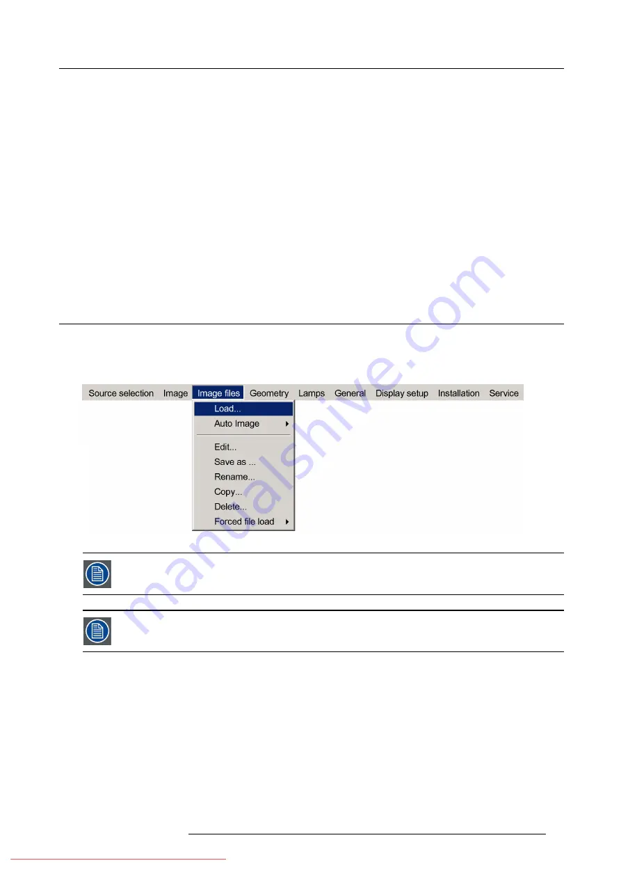
Menu Layout

A grey line (menu separator) indicates the transition between standard and advanced menu parameters.

Three suspension points indicate that the menu item hides a dialog box or a text box.

Image 7-1

The menus inserted in this manual are of the advanced type: all the items are visible. The menus seen by a
standard user on the screen will hence not correspond with the menus in the manual i.e. the advanced items
will not be visible, they will be replaced with "

More..

."

Greyed out menus or menu items are not available

Menu password

The advanced menu items are only visible after entering a password. The default password is ’

0000’

.

This password can be changed in the

Installation

menu.

How to pull down a menu ?

1. Use

to pull down a menu

How to pull down a submenu ?

1. Use

to pull down a submenu

R59770324 SIM 5W 22/12/2011

53

Downloaded From projector-manual.com Barco Manuals

Содержание SIM 5W

Страница 1: ...SIM 5W User guide R59770324 06 22 12 2011 Downloaded From projector manual com Barco Manuals ...

Страница 2: ...s Simulation Division Noordlaan 5 B 8520 Kuurne Phone 32 56 36 82 11 Fax 32 56 36 84 86 Support www barco com esupport Visit us at the web www barco com Printed in Belgium Downloaded From projector manual com Barco Manuals ...

Страница 3: ...service For details please visit the Barco website at http www barco com en AboutBarco weee eCos The software in this product uses eCos the Embedded Configurable Operating System This is the license for eCos Copyright C 1998 1999 2000 2001 2002 2003 Red Hat Inc Copyright C 2002 2003 John Dallaway Copyright C 2002 2003 Nick Garnett Copyright C 2002 2003 Jonathan Larmour Copyright C 2002 2003 Andrew...

Страница 4: ... operated incorrectly or if after the transfer of risks the goods are subject to influences not agreed upon in the contract all guarantee claims of the purchaser will be rendered invalid Not included in the guarantee coverage are system failures which are attributed to programs or special electronic circuitry provided by the purchaser e g interfaces Normal wear as well as normal maintenance are no...

Страница 5: ...9 3 Serial connection 34 4 10 RCU Terminology Overview 36 4 11 Local Keypad Terminology Overview 37 4 12 Diagnose Leds 38 5 Setup 39 5 1 Powering up the projector 39 5 2 Setting up the Remote Control Unit address 39 5 3 Setting up the projector address only if necessary 40 5 4 Setting up the orientation 41 5 5 Adjusting the lens 42 5 6 Setup the baud rate for serial communication 44 5 7 Preference...

Страница 6: ... 7 6 6 6 Shift Adjustment 100 7 6 6 7 Transport Delay 102 7 6 6 8 Sharpness 104 7 6 6 9 Geometry Reset 105 7 6 6 9 1 Reset all levels 105 7 6 6 9 2 Restore to a level 106 7 6 7 Rename a Geometry File 108 7 6 8 Copy a Geometry File 109 7 6 9 Delete a Geometry File 110 7 7 Lamps 111 7 7 1 Lamp runtimes 111 7 7 2 Lamp mode 112 7 7 3 CLO 113 7 7 3 1 The CLO menu 113 7 7 3 2 CLO mode 114 7 7 3 3 CLO Ta...

Страница 7: ...7 9 9 5 Black level 160 7 9 9 5 1 Introduction 160 7 9 9 5 2 Internal black level 161 7 9 9 5 3 Beta planes 162 7 9 9 6 Blanking 163 7 9 10 AutoImage Setup 164 7 9 11 Sync variance limit 165 7 10 Installation 166 7 10 1 EDID 166 7 10 2 Internal patterns 167 7 10 3 Scaled patterns 170 7 10 4 Formatter patterns 171 7 10 5 Color Wheel Index 172 7 11 Service 173 7 11 1 Diagnostics 173 7 11 2 Board ide...

Страница 8: ...Table of contents 4 R59770324 SIM 5W 22 12 2011 Downloaded From projector manual com Barco Manuals ...

Страница 9: ...ned and that the projector complies with Electromagnetic Compatibility requirements it should always be operated with all of it s covers in place Ensure that nothing can be spilled on or dropped inside the projector If this does happen switch off and unplug the mains supply immediately Do not operate the projector again until it has been checked by qualified service personnel The projector must al...

Страница 10: ...1 Safety Instructions 6 R59770324 SIM 5W 22 12 2011 Downloaded From projector manual com Barco Manuals ...

Страница 11: ...099 1 owners manual English 1 owners manual Chinese 1 safety manual Form The projector is packed in a carton box To provide protection during transportation the projector is surrounded with foam The package is secured with banding and fastening clips R824562 R824561 R824518 cable basket R724408 R825784 Projector Image 2 1 Lens packaging The Lens is supplied as an individual item The lens is packed...

Страница 12: ... cardboard cover 4 Remove the large cardboard 5 Remove the 8 foam parts 6 Loosen and remove the 3 screws spacers fixing the projector to the wooden board 7 Remove the projector from the board Save the original shipping carton and packing material they will be necessary if you ever have to ship your projector For maximum protection repack your projector as it was originally packed at the factory 8 ...

Страница 13: ...t excessive dust or humidity Be aware that room heat rises to the ceiling check that temperature near the installation site is not excessive CAUTION Harmful Environmental Contamination Precaution Environment condition check A projector must always be mounted in a manner which ensures the free flow of clean air into the projectors ventilation inlets as well as free flow at the ventilation outlets T...

Страница 14: ... lighting is desirable for illuminating small areas so that interference with the screen is minimal Which screen type There are two major categories of screens used for projection equipment Those used for front projected images and those for rear projection applications Screens are rated by how much light they reflect or transmit in the case of rear projection systems given a determined amount of ...

Страница 15: ...on guidelines 20 roll around projector lens 20 Roll around projector lens 20 Roll around projector lens Image 3 1 Roll possibilities R59770324 SIM 5W 22 12 2011 11 Downloaded From projector manual com Barco Manuals ...

Страница 16: ... an image Image 3 3 Side projection limitations 3 4 Airflow Airflow The Air Intake Vent is located on the bottom side of the projector while the Exhaust Vent can be found on the left rear side of the projector Make sure the projector is installed in a location so that the air inlets and outlets for the cooling system are not obstructed 12 R59770324 SIM 5W 22 12 2011 Downloaded From projector manua...

Страница 17: ...r exhaust vent CAUTION Do not place flammable objects near the Exhaust Vent CAUTION Do not touch the Exhaust Vent Grill when the projector is switched on this part will become hot during operation CAUTION In a multi channel setup make sure that the hot air outlet from the one projector is not sucked in as fresh air by the other projector R59770324 SIM 5W 22 12 2011 13 Downloaded From projector man...

Страница 18: ...3 Installation guidelines 14 R59770324 SIM 5W 22 12 2011 Downloaded From projector manual com Barco Manuals ...

Страница 19: ...s formulas Lens shift limitations Lens brightness Projector configuration Connections RCU Terminology Overview Local Keypad Terminology Overview Diagnose Leds Dimensions Dimensions are given in mm and inch 1inch 25 4 mm Weight projector 15kg R59770324 SIM 5W 22 12 2011 15 Downloaded From projector manual com Barco Manuals ...

Страница 20: ...ng the handle a little towards the bottom of the RCU 2 Lift up the top side of the cover at the same time 3 Insert the batteries as indicated in the RCU 4 Put the battery cover on its place How to replace the batteries in the RCU To replace the batteries 1 Remove the battery cover on the backside by pushing the handle a little towards the bottom of the RCU 2 Lift up the top side of the cover at th...

Страница 21: ...6 or equivalent 7 Put the battery cover on its place Image 4 2 4 2 Lens Installation Necessary tools No tools How to install the Lens 1 Take the lens out of its packing material 2 Make sure the lens lock holder is in the left position R59770324 SIM 5W 22 12 2011 17 Downloaded From projector manual com Barco Manuals ...

Страница 22: ...e lens lock holder is in the left position 3 Lock the lens by placing it in the housing push carefully to lock click sound the lens in the housing Image 4 4 18 R59770324 SIM 5W 22 12 2011 Downloaded From projector manual com Barco Manuals ...

Страница 23: ...ted in the left and bottom position Image 4 6 In case of a Scheimpflug lens insert the lens with the adjustment bolts located in the left and bottom position A Scheimpflug lens will limit shift possibilities Mount the lens depending on the application adjustment bolts located in the left and bottom position to allow maximum shift up and in the left top position to allow maximum shift down CAUTION ...

Страница 24: ...ses Necessary tools TorayseeTM cloth delivered together with the lens kit Order number R379058 How to clean the lens 1 Always wipe lenses with a CLEAN TorayseeTM cloth 2 Wipe lenses in a one single direction Warning Do not wipe back and forwards across the lens surface as this tends to grind dirt into the coating 3 Do not leave the cleaning cloth in either an open room or lab coat pocket as doing ...

Страница 25: ... dh and dv are the distances between the center of the shifted image and the on axis image See image image 4 8 The shift limitations for vertical and horizontal direction are always measured with the orthogonal direction at 0 off axis Maximum vertical and horizontal shift ranges are not necessarily possible at the same time A safe region to shift is shown in image image 4 9 Outside this region mec...

Страница 26: ...0 0 QCLD 0 85 1 SF TP 0 0 0 0 0 0 QCLD 1 1 1 3 1 TP 85 20 105 115 20 135 QCLD 1 1 1 3 1 WA 65 20 85 115 20 135 QCLD 1 1 1 3 1 SF TP 85 20 105 115 20 135 QCLD 1 1 1 3 1 SF WA 65 20 85 115 20 135 Table 4 3 Maximum shift measured for different lenses on this projector On axis image 0 shift vertically and horizontally Off axis image dh Dh Dv Dv a horizontal shift b vertical shift Image 4 8 off axis De...

Страница 27: ...rojection lenses Lens WA TP CLD 1 2 1 6 1 87 68 CLD 1 6 2 4 1 100 80 CLD 2 4 4 3 1 90 75 QCLD 0 85 1 82 82 QCLD 1 1 1 3 1 79 83 Table 4 4 Brightness obtained with different projection lenses The evaluated values in the above table were obtained using on axis position and are based on center lumens ANSI lumen and off axis position values are upto 10 lower 4 8 Projector configuration The different c...

Страница 28: ...ecifications Power input range 90V 254V AC 50 60Hz Power consumption 680W Power cord connection Use the supplied power cord to connect the projector to the wall outlet Plug the female power connector into the male connector at the front left side of the projector Projector DVI D COMPUTER DVI D HDCP COMPUTER Image 4 11 4 9 2 Connections overview Connections Overview The following table gives an ove...

Страница 29: ...RS232 In 11 10 100 Base T In Table 4 5 Connections overview 4 9 3 Composite video Composite video connection A Composite video signal is often available on a yellow cinch connector of a Camera VCR or DVD player in this case you will need an adapter cable cinch BNC to connect to Video input of the RGB board How to connect a composite video signal 1 Connect the BNC connector to the projector s BNC v...

Страница 30: ...Mini Din connector of a camera VCR or DVD player How to connect an S Video connection 1 Connect the mini din connector to the projector s S Video input Projector RECORD POWER VHS DVI D COMPUTER DVI D HDCP COMPUTER Image 4 14 S Video connection 4 9 5 RGB RGB data connection The RGB input consists of 5 BNC 26 R59770324 SIM 5W 22 12 2011 Downloaded From projector manual com Barco Manuals ...

Страница 31: ...nnector R G B H V RGBHV R G B H V RGsB R Gs B RGBS R G B S Table 4 6 How to use the BNC s in case of different RGB signals The RGB 5 BNC input can also be used to connect a component video source see Connecting a Component video source How to connect an RGB signal 1 Connect the 5 or 4 BNC cables to the projector s RGB input Projector DVI D COMPUTER DVI D HDCP COMPUTER Image 4 15 RGB connections 4 ...

Страница 32: ... projector but since this is a protected signal it will not be visible through the DVI out connector DVI OUT This DVI output has the same resolution as the native resolution of the projector 1920x1200 with a vertical refresh rate of 60Hz This can not be changed In case of a selected DVI HDCP source this DVI out will show a black window not the content of the signal 4 9 7 2 Connecting to a DVI conn...

Страница 33: ...nput connection Projector DVI D COMPUTER DVI D HDCP COMPUTER Image 4 18 DVI input connection How to connect a DVI HDCP source 1 Connect the DVI cable to the DVI HDCP IN connector of the projector R59770324 SIM 5W 22 12 2011 29 Downloaded From projector manual com Barco Manuals ...

Страница 34: ... connector of the projector Projector DVI D COMPUTER DVI D HDCP COMPUTER Image 4 20 DVI out connection 4 9 8 PC PC connection A RGB signal can be connected through a DB 15 connector VGA connector How to connect a PC signal 1 Connect the VGA connector to the projector sDB 15 input 30 R59770324 SIM 5W 22 12 2011 Downloaded From projector manual com Barco Manuals ...

Страница 35: ...be a local area network or a small dedicated network Following operations are made possible file transfer for firmware upgrade easy adjustment of projector storage of multiple projector configurations and set ups wide range of control possibilities linking the projectors to allow uniform color Linked Dynacolor and brightness CLO The connection to the projector can be done via a crossed cable or vi...

Страница 36: ...k connection But when the DHCP setting of the projector is set to Yes and the network does not allow the projector to obtain an IP address from the DHCP server the startup time will be delayed by upto five minutes After this time a time out occurs if the network detection fails and the projector starts up without any network connection What can be done These settings are used to set the Ethernet C...

Страница 37: ...Mask this field can be edited when Fixed IP is selected Gateway Gateway this field can be edited when Fixed IP is selected Hostname Hostname this field can be edited when DHCP is selected How to set up the network settings 1 Press the MENU key to activate the Menu bar 2 Push the cursor key or to highlight Installation in the menu bar 3 Push the key to pull down the Installation menu 4 Push the cur...

Страница 38: ...ply settings to apply the changes A dialog box is shown The different executed operations are shown with a checkbox The last operation Restarting network takes a few seconds more Image 4 25 4 9 9 3 Serial connection Serial connection To establish a serial communication with the projector a RJ12 connector is available 34 R59770324 SIM 5W 22 12 2011 Downloaded From projector manual com Barco Manuals...

Страница 39: ... Color RJ12 1 2 Red 3 3 Green 4 4 5 Blue 6 6 7 Black 2 8 Yellow 5 9 Image 4 26 Default setting for the baudrate is 9600 How to make a serial connection 1 Plug in the RJ12 connector Projector DVI D COMPUTER DVI D HDCP COMPUTER Image 4 27 Serial connection R59770324 SIM 5W 22 12 2011 35 Downloaded From projector manual com Barco Manuals ...

Страница 40: ...SE To stop projection for a short time press PAUSE The image disappears but full power is retained for immediate restarting 6 STANDBY Standby button to start projector when the power switch is switched on and to switch off the projector without switching off the power switch Attention Switching to Standby When the projector is running and you want to go to standby press the standby key for 2 secon...

Страница 41: ...u selections to perform bare scale adjustments or to zoom focus when the direct access is active 20 ENTER To start up the adjustment mode or to confirm an adjustment or selection in the adjustment mode 21 BACK To leave the selected menu or item go upwards to previous menu 22 SOURCE Not used 23 Lens control Use these buttons to obtain the desired ZOOM SHIFT and FOCUS 24 STANDBY Standby button to st...

Страница 42: ...own sequence flickers 120 seconds after switching to standby1 Upgrading If blinking upgrading lamp driver Rescue program Software error Led 2 Not used Not used Hardware error If blinking projector busy with passive infitec ON OFF Led 3 IR acknowledgement Not used Standby Status 1 Projector cannot be restarted during this period 38 R59770324 SIM 5W 22 12 2011 Downloaded From projector manual com Ba...

Страница 43: ...rts up without any network connection How to power up the projector 1 Switch the power switch to 1 2 The software will be initialized The initialization is followed by the keypad lighting up briefly and the projector Standby status 5 2 Setting up the Remote Control Unit address RCU Remote Control Unit What has to be done To allow the communication between the RCU and the projector the RCU has to b...

Страница 44: ... by default 0 In other words an RCU set to address 0 will always control a projector regardless of its projector address since it uses the common address 5 3 Setting up the projector address only if necessary What can be done The projector is shipped with projector address set to 0 In some cases the projector address must be changed for example if an unique RCU is used to control 2 or more project...

Страница 45: ...done Depending on the mechanical orientation of the projector the projector s internal settings have to be adapted The projector is shipped default with a table front orientation How to set the orientation 1 Press MENU to activate the Tool bar 2 Press to select the Installation item 3 Press to Pull down the Installation menu 4 Use or to select Orientation 5 Press to pull down the menu 6 Use or to ...

Страница 46: ...enses will also allow you to Zoom and focus the image All these lens parameters can be adjusted using the RCU the local keypad or in the Installation menu of the projector s OSD Zoom only for motorized lenses Focus only for motorized lenses horizontal vertical Shift The lens can also be adjusted via the dedicated keys on the remote How to Zoom focus or shift via the RCU or keypad 1 Press LENS ZOOM...

Страница 47: ... Press to Pull down the Installation menu 4 Use or to select Lens adjustments Image 5 7 5 Press ENTER A text box appears on the screen follow the instructions Image 5 8 Image 5 9 The use of a sheet of paper held in front of the screen can be useful to determine the focus plane position for best focus R59770324 SIM 5W 22 12 2011 43 Downloaded From projector manual com Barco Manuals ...

Страница 48: ...hange the baud rate 1 Press MENU to activate the Tool bar 2 Press to select the Installation item 3 Press to Pull down the Installation menu 4 Use or to select RS232 baud rate Image 5 10 5 Press to pull down the menu 6 Use or to select the desired baud rate 7 Press ENTER Always select the highest rate unless otherwise specified 5 7 Preferences Overview Preferences 5 7 1 Preferences Overview Langua...

Страница 49: ... projector after a power failure breakdown i e without passing through the standby state by recovering the previous settings previous source This function can be disabled if undesired or inadequate for safety reasons CAUTION If the Automatic startup function is enabled one must be aware of the fact that it involves safety precautions Make sure that the projector or the operators will not be affect...

Страница 50: ... password used to access the advanced More items can be reprogrammed How to change the password 1 Press MENU to activate the Tool bar 2 Press to select the Installation item 3 Press to Pull down the Installation menu 4 Use or to select Change password Image 5 13 5 Press ENTER 46 R59770324 SIM 5W 22 12 2011 Downloaded From projector manual com Barco Manuals ...

Страница 51: ...ops by a simple check CLO adding the projector to this control loop will allow the brightness light output of the projector to be controlled by the master Dynacolor adding the projector to this control loop will allow the displayed primary and secondary colors of the projector to be controlled by the Master This information has to be declared in the Master projector since this projector must know ...

Страница 52: ...d 2 Fill in the IP address or Host name of the projector to be declared as slave i e to be controlled by the Master For example IP address 150 158 193 110 3 Select and press ENTER for the desired parameters to be controlled by the master i e CLO and or Dynacolor and or Stereo It is advised to declare the projector by a Host name unique name in the network The Dynacolor options are used to perform ...

Страница 53: ...5 Setup To clear an IP address or Host name from the text box use the C button R59770324 SIM 5W 22 12 2011 49 Downloaded From projector manual com Barco Manuals ...

Страница 54: ...5 Setup 50 R59770324 SIM 5W 22 12 2011 Downloaded From projector manual com Barco Manuals ...

Страница 55: ...l display systems It should be noted that the heat dissipation of the product itself might influence its environment if not monitored and corrected via external responsive temperature controls this might affect the typical settle time required How to start up the projector 1 Press the Standby button on the RCU or the local keypad 9 0 EN T ER M EN U B A C K D I G I Z O O M PH A SE P A U SE PI P L O...

Страница 56: ...6 Getting started C O N T R B R I G H T N C O L O R T IN T PH A SE Image 6 3 52 R59770324 SIM 5W 22 12 2011 Downloaded From projector manual com Barco Manuals ...

Страница 57: ...of the advanced type all the items are visible The menus seen by a standard user on the screen will hence not correspond with the menus in the manual i e the advanced items will not be visible they will be replaced with More Greyed out menus or menu items are not available Menu password The advanced menu items are only visible after entering a password The default password is 0000 This password ca...

Страница 58: ...e control 1 Press ENTER to activate the input field Image 7 2 2 Key in the desired value Entering numeric values using the arrow keys on the remote control 1 Press ENTER to activate the input field 2 Press or to select the digit to be changed Image 7 3 3 Press or to increase or decrease the value Entering numeric values using the arrow keys on the local keypad 1 Press ENTER to activate the input f...

Страница 59: ...ctor For example L1 DVI L2RGB YUVI In this case a DVI board is installed in the first layer L1 a RGB YUV board is installed in the second layer L2 When selecting a source with a different aspect ratio than the projector s native aspect ratio the source can be shown in its native resolution or can be re scaled to the projector s resolution the latter case brings of course some loss of quality This ...

Страница 60: ...called S VHS signal An S Video signal is available on the Mini Din connector of a camera VCR or DVD player Adjustments on a S Video signal The projectors allows different adjustment on a video signal Depending on the type of signal NTSC PAL the terms differ Color adjusts the level of color saturation in a PAL signal Tint adjusts the level of color saturation in an NTSC signal How to select the S V...

Страница 61: ...menu Lx RGB YUV x being the layer on which the RGB signal is connected for example L1 RGB YUV if the signal is connected to layer 1 3 Use or to select Lx RGB YUV 4 Use to open the menu 5 Use or to select RGB or YUV Image 7 6 6 Press ENTER to confirm your choice A bullet indicates the selected source which now appears on the screen Adjustments on an RGB signal The projector allows different adjustm...

Страница 62: ...to the DVI input of the projector These signals are often available on a PC or other image generator How to select the DVI input 1 Press MENU to activate the Tool bar 2 Press to Pull down the Source Selection menu The menu will contain one item Lx DVI x being the layer on which the RGB signal is connected for example L4 DVI if the signal is connected to layer 4 3 Use or to select Lx DVI Image 7 8 ...

Страница 63: ...gs 5 Press to pull down the menu 6 Use or to select Contrast 7 Press ENTER On the screen appears now a slider box Image 7 9 8 Use or the numeric keys on the remote or the keypad to change the contrast 7 4 1 2 Setting the Brightness Brightness adjustment Adjusting the brightness will affect the dark areas of the image Increase the brightness to lighten up the parts that are too dark How to change t...

Страница 64: ...der box Image 7 11 8 Use or the numeric keys on the remote or the keypad to change the color 7 4 1 4 Tint NTSC video signals only Tint adjustment Tint adjustment is only applicable for NTSC video signals The tint adjustment allows the reddish and greenish tones to be corrected How to change the Tint 1 Press MENU to activate the Tool bar 2 Press to select the Image item 3 Press to Pull down the Ima...

Страница 65: ... gradations brightness levels in the projected image Changing the gamma mainly changes the midtones of the image How to adjust the Gamma 1 Press MENU to activate the Tool bar 2 Press to select the Image item 3 Press to Pull down the Image menu 4 Use or to select settings 5 Press to pull down the menu 6 Use or to select Gamma 7 Press ENTER On the screen appears now a slider box Image 7 14 8 Use or ...

Страница 66: ...ct Noise Reduction 7 Press ENTER On the screen appears now a slider box Image 7 16 8 Use or the numeric keys on the remote or the keypad to change the Noise Reduction 7 4 2 Gain control on Video 7 4 2 1 Automatic Gain on Video Automatic Gain on Video is only for Video signals Enabling disabling the Automatic Gain on Video 1 Press MENU to activate the Tool bar 2 Press to select the Image item 3 Pre...

Страница 67: ... Automatic gain control is enabled ON the manual setting does not affect the gain Automatic gain control must therefore be disabled The manual gain control must be done on an external pattern with white areas grey scale bar pattern How to set the Manual Gain Control 1 Press MENU to activate the Tool bar 2 Press to select the Image item 3 Press to Pull down the Image menu 4 Use or to select Setting...

Страница 68: ...es may even use the anamorphic 16 9 or anamorphic 2 35 1 to take advantage of the higher vertical resolution offered by the 4 3 ratio The term anamorphic means that the original wide screen image is squeezed in order to fit the 4 3 aspect ratio 4 3 16 9 2 35 1 Image 7 20 Common non anamorphic aspect ratios in non HDTV DVD sources 16 9 2 35 1 Image 7 21 Anamorphic aspect ratios in non HDTV DVD sour...

Страница 69: ... done The aspect ratio setting forces the projector to project an image using a defined aspect ratio Auto 4 3 16 9 16 10 5 4 Custom The settings do not refer to the aspect ratio of the source R59770324 SIM 5W 22 12 2011 65 Downloaded From projector manual com Barco Manuals ...

Страница 70: ...e information stored in the image files whereas Custom allows to set a personnel ratio Selecting Auto in case of a Video source may shrink the image horizontally The aspect ratio setting only affects the active source window the desktop being locked on the native aspect ratio How to change the Aspect ratio 1 Press MENU to activate the Tool bar 2 Press to select Image 3 Press to Pull down the Image...

Страница 71: ...enabled How to set a custom Aspect ratio 1 Press MENU to activate the Tool bar 2 Press to select Image 3 Press to Pull down the Image menu Image 7 26 4 Use or to select Aspect ratio 5 Use open the Aspect ratio menu 6 Use or to select Custom 7 Press ENTER to confirm A dialog box is displayed Image 7 27 8 Enter the values for width and height of the image The image aspect ratio is updated R59770324 ...

Страница 72: ...e range in which the ADC will work for that particular source this also explains why each input balance setting is linked to a particular source and thus saved in the image file How can it be done To balance the three color signals of a particular source there are conditions in fact we must know the black and the white level of the source i e 1 the considered source must be able to generate a whit...

Страница 73: ...e item 3 Press to Pull down the Image menu 4 Use or to select Input balance 5 Press to pull down the menu 6 Use or to select Automatic Black level 7 Press to pull down the menu 8 Use or to enable ON or to disable OFF Automatic Black level Image 7 32 9 Press ENTER to confirm A white bullet shows the active setting Performing Black input balance 1 Select a black pattern or gray scale as alternative ...

Страница 74: ... part of the image 12 Adjust the Blue black level until bright spots appear on the black part of the image 13 Adjust the Red black level until bright spots appear on the black part of the image The projected image should now be noisy neutral grey If one uses a checkerboard pattern the bright spots should appear in the black blocks Black Level is greyed out if Automatic Black level is enabled ON Pe...

Страница 75: ...white part of the image The projected image should now be noisy neutral grey If one uses a checkerboard pattern the bright spots should appear in the white blocks The input balance settings are stored in the image file each source has its own input balance 7 4 5 Passive InfitecTM Optional Passive InfitecTM Barco InfitecTM is the latest stereo technology it uses high quality color filtering technol...

Страница 76: ... source corresponds to one of these files a custom file is created The custom file is automatically saved if a setting is altered contrast The Save as function allows to create and save a custom file The active file can always be edited in order to fit exactly the source specifications AutoImage creates automatically the best suited image file custom file for a new source AutoImage is used when a ...

Страница 77: ...Press MENU to activate the Tool bar 2 Press to select the Image files item 3 Press to Pull down the Image files menu 4 Use or to select Load Image 7 39 5 Press ENTER A dialog box is displayed Image 7 40 6 Use or to select the desired file Tip For more information specifications on the image files see the Appendix section 7 Press ENTER The file is loaded and the image is adapted What to do if the i...

Страница 78: ... files menu 4 Use or to select Forced file load 5 Press to open the menu 6 Use or to select the desired layer for example Layer 1 7 Press to open the menu 8 Use or to select the desired input Image 7 41 Note Inputs that are not hardware compatible with this layer are greyed out Note if a file is already forced for that input it will be shown on the right 9 Press ENTER The Load dialog box is displa...

Страница 79: ...unch Auto Image 1 Press MENU to activate the Tool bar 2 Press to select the Image files item 3 Press to Pull down the Image files menu 4 Use or to select Auto Image 5 Press to open the menu 6 Use or to select the desired file scan method Image 7 42 7 Press ENTER AutoImage acts on the active window The image in the window may move and change in aspect during the AutoImage process Auto Image can als...

Страница 80: ... is displayed Image 7 44 6 Use or the numeric keys on the remote or the keypad to edit and change the values confirm with ENTER Note greyed out fields can not be updated total pixels Which items can be adjusted The following items can be adjusted Total horizontal pixels Active horizontal pixels Horizontal start in pixels Horizontal period in ns Active vertical lines Vertical start in lines 76 R597...

Страница 81: ... sync locking setting is recommended for poor video signals ex poor TV signals Sharpness adjustment can be chosen to be coarse or fine It is recommended to use the default values Advanced settings for Analog Data sources e g RGB HS VS The advanced button enables the advanced settings for a data source Image 7 47 Color space allows to select between 5 different color spaces RGB ITU_BT_709 SMPTE_240...

Страница 82: ...as create a custom file Creating a custom file When the loaded file is a standard file there is a possibility of saving it as a custom file creating a custom file this is done with the save as function The saved file will always be a custom file saved in the custom directory For sources that are often used a custom file should be created This custom file will then be loaded auto matically and will...

Страница 83: ...he numeric keys on the remote or the keypad to edit and change the values confirm with ENTER Image 7 53 7 5 8 Copy Copy a file The copy function allows to copy a file standard or custom to a custom file to the custom directory How to copy a file 1 Press MENU to activate the Tool bar 2 Press to select the Image files item 3 Press to Pull down the Image files menu 4 Use or to select copy R59770324 S...

Страница 84: ... change the name of the destination file 7 5 9 Delete How to delete a file 1 Press MENU to activate the Tool bar 2 Press to select the Image files item 3 Press to Pull down the Image files menu 4 Use or to select delete 5 Press ENTER A dialog box is displayed Image 7 56 6 Use or to select the desired file 7 Press ENTER 80 R59770324 SIM 5W 22 12 2011 Downloaded From projector manual com Barco Manua...

Страница 85: ... s memory contains a list of files created for demo purposes e g to demonstrate the warping capabilities of the projector These files are called standard files The active file can always be edited in order to fit exactly the screen shape Editing a standard file will automatically create a custom file The file notation in the Geometry files menu describes a file path For example Standard Dist_file1...

Страница 86: ...5 16 17 18 19 20 21 22 26 28 27 32 Image 7 59 The screen is divided in 33x33 regions Modes and Levels The geometry adjustment is divided in 6 groups or modes 2x2 3x3 5x5 9x9 17x17 33x33 These modes represent 21 levels each level represents a group of points or zones Each level will interact with other levels adjusting a point on a certain level will affect points in the levels underneath The level...

Страница 87: ... 21 21 21 21 21 19 20 18 20 19 20 20 21 17 21 21 20 21 19 21 20 21 18 21 20 21 19 21 21 20 21 21 21 21 21 21 19 20 18 20 19 20 20 21 17 21 21 20 21 19 21 20 21 18 21 20 21 19 21 21 20 21 21 21 21 21 21 19 20 18 20 19 20 20 21 17 21 21 20 21 19 21 20 21 18 21 20 21 19 21 21 20 21 21 21 21 21 21 19 20 18 20 19 20 20 21 17 21 21 20 21 19 21 20 21 18 21 20 21 19 21 21 20 21 21 21 21 21 21 19 20 18 20 ...

Страница 88: ...the 2x2 points Adjusting points on level 1 will affect level 2 till 21 At the bottom of the structure we find the 33x33 points adjustment adjusting grid points on level 21 will not affect any other points these are called local points 7 6 5 Load How to load a geometry file 1 Press MENU to activate the Tool bar 2 Press to select Geometry 3 Press to Pull down the Geometry menu 4 Press to select Load...

Страница 89: ... generated internally by the projector see internal patterns Overview Accessing the Geometry Edit menu Geometry Edit wizard Geometry Edit Modes Editing a geometry file Axis link Shift Adjustment Transport Delay Sharpness Geometry Reset 7 6 6 1 Accessing the Geometry Edit menu How to access the Geometry Edit menu 1 Press MENU to activate the Tool bar 2 Press to select Geometry 3 Press to Pull down ...

Страница 90: ...the Edit dialog box is displayed When selecting a point in a certain adjustment a yellow box shows the selection and a blue dotted box is placed around the selected grid point indicating the interaction zone Image 7 64 86 R59770324 SIM 5W 22 12 2011 Downloaded From projector manual com Barco Manuals ...

Страница 91: ...eometry corrections This gives the user real time access to the distortion characteristics Each individual point can be selected and shifted to the desired location in real time Depending on the geometry mode the dialog box may slightly differ the dialog box below is for a 2x2 mode adjustment Image 7 66 Field adjustment Description Notes Level 2x2 gives the selected geometry adjustment In this cas...

Страница 92: ...it box allows to edit the position of the point along the y axis Axislink see Axislink Modes see Geometry Edit Modes Table 7 2 dialog box legend When applying a distortion to the image this may take a certain time During this operation a text box is shown Busy Image 7 67 Busy message 7 6 6 3 Geometry Edit Modes The geometry Edit Modes Select mode allows to select the desired area on the screen usi...

Страница 93: ...7 Advanced Image 7 68 Image 7 69 Image 7 70 R59770324 SIM 5W 22 12 2011 89 Downloaded From projector manual com Barco Manuals ...

Страница 94: ...21 19 21 20 21 18 21 20 21 19 21 21 20 21 21 21 21 21 21 19 20 18 20 19 20 20 21 17 21 21 20 21 19 21 20 21 18 21 20 21 19 21 21 20 21 21 21 21 21 21 19 20 18 20 19 20 20 21 17 21 21 20 21 19 21 20 21 18 21 20 21 19 21 21 20 21 21 21 21 21 21 19 20 18 20 19 20 20 21 17 21 21 20 21 19 21 20 21 18 21 20 21 19 21 21 20 21 21 21 21 21 21 19 20 18 20 19 20 20 21 17 21 21 20 21 19 21 20 21 18 21 20 21 1...

Страница 95: ...Note that in this mode 3 levels are involved level 4 5 and level 6 previous adjusted points are left out 31 30 0 10 9 8 7 6 5 1 4 3 2 25 29 24 23 11 12 13 14 15 16 17 18 19 20 21 22 26 28 27 32 31 30 0 10 9 8 7 6 5 1 4 3 2 25 29 24 23 11 12 13 14 15 16 17 18 19 20 21 22 26 28 27 32 7 7 7 7 7 7 7 7 7 7 7 7 7 7 7 7 8 8 8 8 9 9 9 9 9 9 9 9 9 9 9 16 16 16 16 16 16 16 16 16 16 16 16 16 16 16 16 16 16 1...

Страница 96: ...ect mode is enabled and the top left row 0 colom 0 corner is selected Image 7 74 Image 7 75 How to select another point 1 Press to select the next adjustment point 92 R59770324 SIM 5W 22 12 2011 Downloaded From projector manual com Barco Manuals ...

Страница 97: ...anced The column is adapted to 32 Image 7 76 Image 7 77 2 Press to select the next adjustment point The row is adapted to 32 R59770324 SIM 5W 22 12 2011 93 Downloaded From projector manual com Barco Manuals ...

Страница 98: ...7 Advanced Image 7 78 Image 7 79 3 Press to select the next adjustment point 94 R59770324 SIM 5W 22 12 2011 Downloaded From projector manual com Barco Manuals ...

Страница 99: ...using the Adjust mode Adjusting point row 0 column 0 by 100 pixels along the x axis in the 2x2 mode 1 Press ENTER to go to the Adjust Mode The Adjust mode is selected R59770324 SIM 5W 22 12 2011 95 Downloaded From projector manual com Barco Manuals ...

Страница 100: ...ne in small steps Adjusting for instance from 0 to 100 using the Adjust mode is not the ideal method The use of the Edit and Change mode is more appropriate How to adjust using the Edit and Change mode Adjusting point row 0 column 0 by 100 pixels along the x axis in the 2x2 mode 1 Press 2 times ENTER to go to the Edit Mode 96 R59770324 SIM 5W 22 12 2011 Downloaded From projector manual com Barco M...

Страница 101: ...it and use and to increment decrement the digit Tip One can also use the numeric digits to fill in the desired value The image is distorted along the X axis Notice the unaffected regions 7 6 6 5 Axis link What is AxisLink When AxisLink is set to On the adjustment coordinate system will coincide with the edges of the distorted image R59770324 SIM 5W 22 12 2011 97 Downloaded From projector manual co...

Страница 102: ...ith AxisLink set On and Off 1 Start with a non distorted image assume the left top corner is selected 0 0 Image 7 86 2 Shift the left top corner 300 pixels to the left 0 0 Image 7 87 98 R59770324 SIM 5W 22 12 2011 Downloaded From projector manual com Barco Manuals ...

Страница 103: ...sult in a quick adjustment when dealing with complex setups AxisLink OFF The coordinate system used for the adjustment is absolute Y 300 216 300 300 300 X Y Y 3 0 0 AxisLink OFF AxisLink ON X Y X Y X Y Image 7 88 How to set AxisLink ON 1 Start up the Geometry Edit menu 2 The Edit mode is selected R59770324 SIM 5W 22 12 2011 99 Downloaded From projector manual com Barco Manuals ...

Страница 104: ...ble to shift the whole image This is considered as a displacement of the 4 corner points of the 2x2 mode The same dialog box is used as for the geometry edit How to use the Shift adjustment 1 Start up the Geometry Edit menu 2 Press to select Shift 3 Press ENTER A dialog box is displayed Note that In the shift adjustment the Adjust mode is selected by default instead of the Select mode for the othe...

Страница 105: ...e Edit mode is selected Image 7 91 5 Use and to select the PixelsX edit box The PixelsX edit box is focused Image 7 92 6 Press ENTER R59770324 SIM 5W 22 12 2011 101 Downloaded From projector manual com Barco Manuals ...

Страница 106: ...along the X axis Image 7 94 Geometry Shift 8 Press BACK to return to the Geometry Edit menu 7 6 6 7 Transport Delay What is Transport Delay The Transport Delay is the interval between the time at which an image frame is received from the first FPGA of the PMP and the time at which the processing of this frame starts in the second FPGA of the PMP 102 R59770324 SIM 5W 22 12 2011 Downloaded From proj...

Страница 107: ... but pixel x 1 of the original line 1 This means that every pixel which comes before pixel x in the original line 1 must be stored in a temporary memory before the processing of the frame can start Image 7 96 Transport Delay basic principle The Transport delay can be adjusted manually or can be set to automatic A short Transport delay creates a small delay with respect to the source but a large de...

Страница 108: ...y Note The Transport Delay is by default set to 200 The Transport Delay Range can be set from 0 to 1023 Tip When the transport delay needs to be adjusted In a multi channel setup first adjust the transport delay of all projectors one by one leave the projector with the maximum value then set all other projectors to this maximum value 3 Press BACK to return to the Geometry Edit menu 7 6 6 8 Sharpne...

Страница 109: ...ocal keypad to edit and change the value of the Sharpness Note The Sharpness can be set from 8 to 8 4 Press BACK to return to the Geometry Edit menu 7 6 6 9 Geometry Reset Overview Reset all levels Restore to a level 7 6 6 9 1 Reset all levels How to reset all levels 1 Start the Geometry Edit menu 2 Push or to select Reset 3 Push the key to pull down the menu 4 Push or to highlight Reset all level...

Страница 110: ...return to the Geometry Edit menu 7 6 6 9 2 Restore to a level What can be done Restore to a level means that all the higher level geometry corrections are reset all geometry correction values are set to 0 The correction values of the level and all the lower levels are kept 106 R59770324 SIM 5W 22 12 2011 Downloaded From projector manual com Barco Manuals ...

Страница 111: ...evel How to restore to a level 1 Start the Geometry Edit menu 2 Push or to select Reset 3 Push the key to pull down the menu 4 Push or to highlight the desired level to restore Restore to R59770324 SIM 5W 22 12 2011 107 Downloaded From projector manual com Barco Manuals ...

Страница 112: ... in the image by a more or less accentuated jump 5 Press BACK to return to the Geometry Edit menu 7 6 7 Rename a Geometry File How to rename a geometry file 1 Start up the Geometry menu 2 Press to select Rename Image 7 105 3 Press ENTER 108 R59770324 SIM 5W 22 12 2011 Downloaded From projector manual com Barco Manuals ...

Страница 113: ...gh the characters 5 Press ENTER The file is renamed 6 Press BACK to return to the Geometry Edit menu 7 6 8 Copy a Geometry File How to Copy a Geometry File 1 Start up the Geometry menu 2 Press to select Copy Image 7 107 3 Press ENTER A dialog box is displayed R59770324 SIM 5W 22 12 2011 109 Downloaded From projector manual com Barco Manuals ...

Страница 114: ...ocal keypad to edit and change the values confirm with ENTER 7 Press BACK to return to the Geometry Edit menu 7 6 9 Delete a Geometry File How to Delete a Geometry File 1 Start up the Geometry menu 2 Press to select Delete Image 7 109 3 Press ENTER A dialog box is displayed Image 7 110 110 R59770324 SIM 5W 22 12 2011 Downloaded From projector manual com Barco Manuals ...

Страница 115: ... the Geometry Edit menu 7 7 Lamps Overview Lamp runtimes Lamp mode CLO Dimmer control History Reset lamp runtime Clear lamp error Lamp runtime warning 7 7 1 Lamp runtimes How to display the lamp runtimes 1 Press MENU to activate the Toolbar 2 Press to select the Lamp item 3 Press to Pull down the Lamp menu 4 Use or to select Runtimes Image 7 112 5 Press ENTER R59770324 SIM 5W 22 12 2011 111 Downlo...

Страница 116: ...switches automatically to the other lamp without interrupting the projection The failure is logged and the lamp will never be initialized in the future Dual mode Both lamps are working When one lamp fails the projector continues the projection using the remaining lamp How to select the lamp mode 1 Press MENU to activate the Toolbar 2 Press to select the Lamp item 3 Press to Pull down the Lamp menu...

Страница 117: ...menu of the projector over a certain period This will eliminate uncontrolled light output drop caused by natural aging of the lamp The light output is checked every 30 seconds and if the target is not met the CCD is adjusted If the CLO is disabled there is no more automatic dimmer adjustment depending of the light output In this mode the light output settings can be done manually In the illustrati...

Страница 118: ...d without the Night Vision option This means that Time of Day is not available Night Vision is an option that can be ordered with the projector 7 7 3 2 CLO mode How to switch ON OFF the CLO 1 Press MENU to activate the Tool bar 2 Press to select the Lamps item 3 Press to Pull down the Lamps menu 4 Use or to select CLO 5 Press to pull down the CLO menu 6 Use or to select Mode 7 Press to pull down t...

Страница 119: ...put target for both CLO and Time of Day is set in this menu This light output value will be forced on the projector provided that the CLO mode has been set to ON Three targets can be set a CLO target in normal mode a CLO target in Infitec stereo mode a Time of Day target If CLO is active and Time of Day is set to x the light output of the projector will be forced to x of the CLO target Each time t...

Страница 120: ... mode How to set the CLO target in InfitecTM mode 1 Press MENU to activate the Tool bar 2 Press to select the Lamps item 3 Press to pull down the Lamps menu 4 Use or to select CLO 5 Press to pull down the CLO menu 6 Use or to select Targets 7 Press to pull down the Targets menu 8 Use or to select Infitec Mode Image 7 120 9 Press ENTER 116 R59770324 SIM 5W 22 12 2011 Downloaded From projector manua...

Страница 121: ...e target for Time of Day 1 Press MENU to activate the Tool bar 2 Press to select the Lamps item 3 Press to pull down the Lamps menu 4 Use or to select CLO 5 Press to pull down the CLO menu 6 Use or to select Targets 7 Press to pull down the Targets menu 8 Use or to select Time of Day Image 7 122 9 Press ENTER A dialog box is displayed Image 7 123 10 Use or the numeric keys on the remote or the key...

Страница 122: ... can be done The light output of the projector can be dimmed using the Set positions menu If the projector has the Night Vision option both the CCD and ECR dimmer can be set separately in the dialogbox It the Night Vision option is not present only the CCD value can be set In this case nor the slider box nor the edit box for the ECR setting will be visible The target settings of the CLO menu are p...

Страница 123: ...rast Ratio to 100 7 7 4 2 Dimmer presets What can be done Four dimmer presets can be stored in the projector In case of a projector without Night Vision option only a value for CCD can be entered in each preset the ECR column is not visible In case of a projector with the Night Vision option each preset includes a value for both CCD and ECR The target settings of the CLO menu are prior to the Pres...

Страница 124: ... set the Presets 1 Press the MENU key to activate the Menu bar 2 Push the cursor key or to highlight Lamps in the menubar 3 Push the key to pull down the Lamps menu 4 Push the cursor key or to highlight Dimming Control 5 Push the key to pull down the Dimming Control menu 6 Push the cursor key or to select Presets and press ENTER to select Image 7 128 120 R59770324 SIM 5W 22 12 2011 Downloaded From...

Страница 125: ...nually set a Time of Day value However In case CLO mode has been set to ON the projector will be set to the target value of Time of Day in the CLO menu instead of the Manual Time of Day value This menu item will be greyed out if the Night Vision options is not present How to manually set the Time of Day 1 Press the MENU key to activate the Menu bar 2 Push the cursor key or to highlight Lamps in th...

Страница 126: ...Limits What can be done It is possible to set limit values for both CCD and ECR dimmer in case of a projector with Night Vision option Too low values for CCD and ECR can lead to artefacts in the image Start halfway and lower the value to find the point where artefacts start to show This value can be entered as a limit In this way the projector will not allow the dimmer value to drop below this lim...

Страница 127: ... the MENU key to activate the Menu bar 2 Push the cursor key or to highlight Lamps in the menubar 3 Push the key to pull down the Lamps menu 4 Push the cursor key or to highlight Dimming Control 5 Push the key to pull down the Dimming Control menu 6 Push the cursor key or to highlight Limits 7 Push the key to pull down the Limits menu 8 Push the cursor key or to select ECR and press ENTER to selec...

Страница 128: ...tivate the Tool bar 2 Press to select the Lamps item 3 Press to Pull down the Lamps menu 4 Use or to select History Image 7 136 5 Press ENTER A text box is displayed Image 7 137 7 7 6 Reset lamp runtime When to reset the lamp runtime The lamp runtime should only be reset when placing a new lamp WARNING Lamp runtime reset as well as the lamp replacement can only be done by a Barco authorized techni...

Страница 129: ...f the new lamp 7 7 7 Clear lamp error Lamp error When a failure of one of the lamps has occurred a lamp logo is displayed in the left corner of the screen This logo will thus always inform the user on a previous lamp error Once the error has been solved or and the lamp has been replaced one can remove clear the lamp error If the error has been cleared without solving the lamp problem the logo will...

Страница 130: ...0 hours before end of lamp lifetime This warning message can be removed by hitting Back on the RCU When the Warning messages are disabled in the hidden Service menu the lamp runtime warning will only be displayed at the next startup of the projector not during a session Enabling or disabling TextBox does not affect the display of the lamp runtime warning How to set the lamp runtime warning 1 Press...

Страница 131: ...cation Image 7 142 5 Press ENTER On the screen appears a text box Image 7 143 6 Press MENU or BACK to exit or to go back to the previous menu 7 8 2 Pause Pause The Pause function allows to stop the image display the projector remaining with full power for immediate restart The image display is interrupted and the projected background is black How to pause the image display 1 Press MENU to activate...

Страница 132: ...e Image 7 145 5 Press ENTER to activate the Freeze function The image can also be frozen using the FREEZE key on the RCU 7 8 4 Standby Timer What can be done If there is no signal and the standby timer is enabled a dialog box is displayed and the projector will shut down after a pre determined time The countdown time can be set in a dialog box in a range from 180 to 3600 seconds default value 300 ...

Страница 133: ...al a PC can then be used to manage the projector sources which act as source windows on top of the desktop image An Ethernet link between the desktop PC and the projector allows the control of the source windows How to enable the desktop 1 Press MENU to activate the Tool bar 2 Press to select General 3 Press to Pull down the General menu 4 Use or to select Desktop 5 Press to open the menu 6 Use or...

Страница 134: ...ull down the Display setup menu 4 Use or to select Textbox 5 Press to pull down the menu 6 Use or to enable ON or disable OFF the textbox Image 7 149 7 Press ENTER A white bullet shows the active setting 7 9 2 Full screen synchronous representation What can be done In the full screen mode the projector will always try to lock on the input source Some monitors connected on the DVI output of the pro...

Страница 135: ...enu 6 Use or to select ON enable OFF disable 7 Press ENTER Image 7 150 7 9 3 Menu bar position What can be done The menu tool bar can be centered vertically the range being from top of the screen to the middle of the screen This can be useful in applications where the top image content is not displayed soft edge region How to center the menu 1 Press MENU to activate the tool bar 2 Press to select ...

Страница 136: ... activate the Tool bar 2 Press to select the Display setup item 3 Press to Pull down the Display setup menu 4 Use or to select Status bar position Image 7 152 5 Press ENTER 6 Use or to position the status bar 7 9 5 Slider box position What can be done The slider box function allows to display or hide the different boxes used for instance for picture settings contrast How to reposition the slider b...

Страница 137: ...witch between the two 7 9 6 DynaColor Overview Introduction Enabling DynaColor DynaColor sets Dynacolor adjustments 7 9 6 1 Introduction What can be done DynaColor will eliminate channel to channel color variations or in case of a single projector force a desired color reproduction How to define color The CIE chromaticity diagram is one way to plot the colors the human eye can see Image 7 154 The ...

Страница 138: ...nents the x y values of this color gamut of each projector will differ Image 7 156 The color gamut of each projector will differ When working with a multichannel setup these color differences between different projectors can be smooth out by matching the color gamuts of the different projectors to a Common Color Gamut Image 7 157 Common Color Gamut The Common Color Gamut In a basic setup with 2 pr...

Страница 139: ...c White Common Color Gamut The following parameters can be adjusted within DynaColor the x y coordinates and L ight Output of the 6 Common Color Gamut perimeter points the x y coordinates and L ight Output of the White point of the Common Color Gamut The Dynacolor Interface Following parameters are available in the Dyancolor Interface Measured Values By default these values are the result of the m...

Страница 140: ...rdinates for the red point Red L Red light output Red Lmax Maximum available red light output Green x y Coordinates for the green point Green L Green light output Green Lmax Maximum available green light output Blue x y Coordinates for the blue point Blue L Blue light output Blue Lmax Maximum available blue light output Cyan x y Coordinates for the cyan point Cyan L Cyan light output Cyan Lmax Max...

Страница 141: ... What can be done Enabling the DynaColor will change the colors to the desired colors mentioned in the DynaColor menu Disabling DynaColor will keep the original colors determined by the source and the projector s optical path How to start up Dynacolor 1 Press MENU to activate the Tool bar 2 Press to select the Display setup item 3 Press to Pull down the Display setup menu 4 Use or to select Dynaco...

Страница 142: ...the following procedures we will only use set1 How to select a Dynacolor set 1 Press MENU to activate the Tool bar 2 Press to select the Display setup item 3 Press to Pull down the Display setup menu 4 Use or to select Dynacolor 5 Press to open the menu 6 Use or to select Active Set 7 Press to open the menu 8 Use or to select for example Set1 Image 7 161 9 Press ENTER 138 R59770324 SIM 5W 22 12 20...

Страница 143: ...es and force them on all the linked slave projectors 7 9 6 4 2 Calibration for the standard mode for multiple projectors What has to be done The calibration of Dynacolor consists of measuring the color values of each projector The measurements have to be done in a dark environment Make sure all external lights are off even a PC screen can produce too much unwanted light Use a light meter PR655 LMT...

Страница 144: ...same way as you did for the red color Note When all colors has been measured and all values has been filled out the Dynacolor main dialog box will appear again 7 The values are finally updated in the measured values of the Dynacolor dialog box 8 Press Default desired to copy the measured values for red green and blue and to calculate the secondary colors cyan yellow and magenta 140 R59770324 SIM 5...

Страница 145: ...values 1 calculate the common values and fill them in the Desired values of both projectors Both projectors will now operate within the same color gamut Automatically Link Set 1 Start up the Linked Projector menu of the Master projector 2 In the Linked Projector menu press the Link Set 1 button R59770324 SIM 5W 22 12 2011 141 Downloaded From projector manual com Barco Manuals ...

Страница 146: ...color values 1 Calculate the common values and fill them in the Desired values of both projectors Both projectors will now operate within the same color gamut Automatically Link Set 1 Start up the Linked Projector menu of the Master projector 2 In the Linked Projector menu press the Link Infitec Set button The common color values are automatically calculated based on the measured values of both pr...

Страница 147: ...to the slave projectors How to select a preset color temperature 1 Press MENU to activate the Tool bar 2 Press to select the Display setupitem 3 Press to Pull down the Display setup menu 4 Use or to select Color temperature 5 Press to pull down the menu 6 Use or to select the desired preset color temperature 7 Press ENTER The color temperature of the image is adapted and a bullet shows the active ...

Страница 148: ...r DynaColor the Brilliant Color mode will be forced from the master to the slave projectors as well How to activate the Brillant ColorTM mode 1 Press the MENU key to activate the Menu bar 2 Push the cursor key or to highlight Display setup in the menu bar 3 Push the key to pull down the Display setup menu 4 Push the cursor key or to highlight Brilliant Color mode and press ENTER to select Image 7 ...

Страница 149: ...ulation of the light output in the overlap zone so that the light output in that zone equals the light output of the rest of the image Adjustable overlapping area 50 100 50 100 image 2 image 1 image 2 image 1 Light output per image Total composite light output Image 7 170 Soft Edge Basic Principle Internal versus external Alpha planes The projector offers 2 methods to achieve soft edging 1 Interna...

Страница 150: ... 6 months license R9893301 for a full license Note that the soft edges are placed on the distorted image i e it surrounds the limits of the distorted image 7 9 9 2 Soft edge adjustments What can be done The soft edge adjustment consists of the adjustment of one or more edges of the image Each zone where the blending is to be applied is divided in 16 zones delimited by 25 adjustments points These p...

Страница 151: ...s adjusting a point on a certain level will affect points in the levels underneath The level of the adjustment gives a measure of this impact A level 1 adjustment happens on the 4 corners of the soft edge zone and will thus affect the whole zone whereas a level 6 will only affect the adjusted point called local points The image below shows the levels in the left side soft edge zone R59770324 SIM 5...

Страница 152: ...l hierarchy On top of this hierarchy the level 1 points Adjusting points on level 1 will affect level 1 till 6 At the bottom of the structure we find the level 6 points adjusting on level 6 will not affect any other points these are called local points 7 9 9 3 Accessing the Soft edge menu How to access the Soft edge menu 1 Press MENU to activate the Tool bar 2 Press to select Display setup 3 Press...

Страница 153: ...Alpha planes 7 9 9 4 1 The soft edge edit wizard The geometry wizard When entering the Edit mode the Edit dialog box is displayed Description of the Edit dialog box An intuitive user interface is used to perform all the Soft edge adjustments Image 7 177 R59770324 SIM 5W 22 12 2011 149 Downloaded From projector manual com Barco Manuals ...

Страница 154: ...d image during the soft edge adjustment Hierarchy level Allows to select the level of the adjustment Reset The soft edge shape is set to default settings Soft edge shape follows geometry settings the shape of the soft edge is set to 12 5 enabled edges stay enabled disabled edges stay disabled Table 7 7 dialog box legend 7 9 9 4 2 The soft edge edit modes The Edit Modes Select mode allows to select...

Страница 155: ...l create an internal soft edge where we will adjust the left side zone displace one point along the x axis How to start up the edit dialog box 1 Press the MENU key to activate the Tool bar 2 Push the cursor key or to highlight Display setup 3 Push the key to pull down the menu 4 Push or to select Soft edge and alpha beta planes 5 Push the key to pull down the menu 6 Push the cursor key or to highl...

Страница 156: ...be displayed How to select the soft edge type The internal soft edge type is selected by default 1 Push or to select the Internal check box The item is focused Image 7 183 2 Press ENTER 152 R59770324 SIM 5W 22 12 2011 Downloaded From projector manual com Barco Manuals ...

Страница 157: ...ge is selected Image 7 184 How to enable the soft edges 1 Push or to select the desired Edges check box The item is focused Image 7 185 2 Press ENTER R59770324 SIM 5W 22 12 2011 153 Downloaded From projector manual com Barco Manuals ...

Страница 158: ...dge is applied on the selected edges How to select the source background 1 Push or to select the desired Source check box in this case we will perform the adjustment on a Full white background The item is focused Image 7 187 2 Press ENTER 154 R59770324 SIM 5W 22 12 2011 Downloaded From projector manual com Barco Manuals ...

Страница 159: ...image is displayed with the soft edges on the 4 sides Image 7 188 Image 7 189 How to enable the adjustment guide 1 Push or to select the check box ON to enable the adjustment guide R59770324 SIM 5W 22 12 2011 155 Downloaded From projector manual com Barco Manuals ...

Страница 160: ...cused Image 7 190 2 Press ENTER The selected check box is checked and the guide is displayed vertical and horizontal grey scale bars Image 7 191 156 R59770324 SIM 5W 22 12 2011 Downloaded From projector manual com Barco Manuals ...

Страница 161: ... 1 Push or to select the hierarchy level slider box The item is focused Image 7 193 2 Use the and to select the level from 1 to 6 How to adjust the soft edge 1 Press Adjust R59770324 SIM 5W 22 12 2011 157 Downloaded From projector manual com Barco Manuals ...

Страница 162: ...ows to select the desired field 5 Press ENTER to edit the field The edit field is put in the edit mode 6 Use the arrows or the digits to fill in the desired x position of the selected point in this case the left top point of level 1 7 Press ENTER to confirm The selected point is displaced to the new position x 100 Y 0 Image 7 195 8 Press BACK to exit 158 R59770324 SIM 5W 22 12 2011 Downloaded From...

Страница 163: ...as follows alpha tiff The free storage capacity on the D drive is about 8 MB it is needed to store the image files geometry files factory backup Alpha planes and Beta planes Practically about 6 MB will be available for the Alpha Beta plane The alpha plane will only be applied if it has been activated in the Edit menu s dialog box see procedure below How to activate an alpha plane 1 Press the MENU ...

Страница 164: ...act on the brightness of the black color of the image part situated outside the soft edge zones Internal black level versus Beta Planes In the same way as for the soft edge adjustment Internal vs Alpha planes this black level adjustment can be fixed internally by using a dialog box or externally by uploading a user defined Beta plane This beta plane will contain the values for the brightness offse...

Страница 165: ...lack level What can be done Internal black level can be adjusted via the projector s software using a dialog box The dialog box allows to add an offset to the black level of the image in the zones outside the soft edge zones The range goes from 0 to 255 How to adjust the internal black level 1 Press the MENU key to activate the Tool bar 2 Push the cursor key or to highlight Display setup 3 Push th...

Страница 166: ... a Beta plane file Beta planes must be uploaded in the following projector directory accessible via FTP D display Softedge The file must be named as follows beta tiff The free storage capacity on the D drive is about 8 MB it is needed to store the image files geometry files factory backup Alpha planes and Beta planes Practically about 6 MB will be available for the Alpha Beta plane The Beta plane ...

Страница 167: ...en and to hide unwanted image information or noise or to put two images next to each other without overlap soft edge This is also called stitching The adjustment of hard edges is done in the same menu as the soft edge with the Edges disabled unchecked How to setup a hard edge shape 1 Press the MENU key to activate the Tool bar 2 Push the cursor key or to highlight Display setup 3 Push the key to p...

Страница 168: ...ne and uses this information to adapt the image to the display AutoImage can adapt the image based on following data Total pixels lines Start pixel lines Phase Contrast brightness levels AutoImage works only for data signals To launch Autoimage see AutoImage in the Image files menu How to set up AutoImage 1 Press MENU to activate the Tool bar 2 Press to select the Display setup item 3 Press to Pul...

Страница 169: ... can be done The sync variance limit is the time in milliseconds by which the processing of the source signal is delayed How to set the Sync variance limit 1 Press MENU to activate the Tool bar 2 Press to select the Display setup item 3 Press to Pull down the Display setup menu 4 Use or to select Sync variance limit Image 7 206 R59770324 SIM 5W 22 12 2011 165 Downloaded From projector manual com B...

Страница 170: ...contains all off the possible resolutions that can be handled by this projector Native this file only contains the native resolution of the projector The latter forces the IG to switch to this native resolution How to switch to a specific EDID file 1 Press MENU to activate the Tool bar 2 Press to select the Installation menu 3 Press to Pull down the menu 4 Use or to select EDID 5 Press to pull dow...

Страница 171: ...ternal patterns which can be used for adjustment purposes Geometry adjustments can not be used on these internal patterns Outline Image 7 209 Outline Hatch Image 7 210 Hatch Color bars Image 7 211 Color bars R59770324 SIM 5W 22 12 2011 167 Downloaded From projector manual com Barco Manuals ...

Страница 172: ... 212 Checkerboard Full white HGBWS Image 7 213 HGBWS Character set H pattern Image 7 214 H pattern Convergence Image 7 215 Convergence ANSI Focus MCW 168 R59770324 SIM 5W 22 12 2011 Downloaded From projector manual com Barco Manuals ...

Страница 173: ...nal pattern 1 Press MENU to activate the Tool bar 2 Press to select the Installation menu 3 Press to Pull down the menu 4 Use or to select Internal Patterns Image 7 217 5 Press to Pull down the menu 6 Use or to select the desired internal pattern 7 Press ENTER The active selection is shown with a white bullet R59770324 SIM 5W 22 12 2011 169 Downloaded From projector manual com Barco Manuals ...

Страница 174: ... Image 7 219 Scaled patterns Gray levels Moving hatch Stereo pattern Image 7 220 Scaled patterns Stereo pattern Purity Composite pattern Dark gray pattern How to select an scaled pattern 1 Press MENU to activate the Tool bar 2 Press to select the Installation menu 3 Press to Pull down the menu 4 Use or to select Scaled Patterns 170 R59770324 SIM 5W 22 12 2011 Downloaded From projector manual com B...

Страница 175: ...rmatter patterns will be distorted according to the active Geometry File Grid Horizontal ramp Vertical ramp Horizontal lines Vertical lines TI checkerboard Checkerboard How to select an Formatter pattern 1 Press MENU to activate the Tool bar 2 Press to select the Installation menu 3 Press to Pull down the menu 4 Use or to select Formatter Patterns R59770324 SIM 5W 22 12 2011 171 Downloaded From pr...

Страница 176: ...d service personnel when a new color wheel is installed The Color Wheel Index must be adjusted until no more vertical lines are visible in the horizontal color bar pattern How to set the Color Wheel Index 1 Press the MENU key to activate the Menu bar 2 Push the cursor key or to highlight Installation in the menubar 3 Push the key to pull down the Installation menu 4 Push the cursor key or to highl...

Страница 177: ... Operation options Version table Restore factory settings Air pressure 7 11 1 Diagnostics What can be done The projector bus allows the diagnostic of different hardware components divided in two main groups I2C diagnostics a number of internal electronic boards can be diagnosed and a graphical interface shows whether an error is Lamps and power supply lamp temperature and power related failures ar...

Страница 178: ...e 7 226 How to display the Lamps and power supply diagnostic menu 1 Press MENU to activate the Tool bar 2 Press to select the Service item 3 Press to Pull down the menu 4 Use or to select Diagnostics 5 Press to pull down the menu 6 Use or to select Lamps and power supply and press ENTER Image 7 227 174 R59770324 SIM 5W 22 12 2011 Downloaded From projector manual com Barco Manuals ...

Страница 179: ...in front of the board s name indicates that the board is functioning in a correct way a red radio bullet indicates an error How to display the Board identification 1 Press MENU to activate the Tool bar 2 Press to select the Service item 3 Press to Pull down the menu 4 Use or to select Board identification Image 7 229 5 Press ENTER R59770324 SIM 5W 22 12 2011 175 Downloaded From projector manual co...

Страница 180: ...at Barco How to activate a new purchased option 1 Press MENU to activate the Tool bar 2 Press to select the Service item 3 Press to Pull down the menu 4 Use or to select Option key Image 7 231 5 Press ENTER A dialog box is displayed Image 7 232 6 Fill in the key by using the digit and the arrow keys 176 R59770324 SIM 5W 22 12 2011 Downloaded From projector manual com Barco Manuals ...

Страница 181: ...be done This procedure is meant to calibrate the dimmer the dimmer is set to its reference positions How to start the Dimmer Reference Positions dialog box 1 Press the MENU key to activate the Menu bar 2 Push the cursor key or to highlight Service in the menubar 3 Push the key to pull down the Service menu 4 Push the cursor key or to highlight Dimming 5 Push the key to pull down the Dimming menu 6...

Страница 182: ...to highlight the Ref Search button and press ENTER Image 7 235 The dimmers are set to the reference positions 2 Use the arrow keys on the RCU to highlight the double right arrow button for Dimmer 1 Image 7 236 3 Press the double right arrow key until the dimmer appears on the top edge of the screen 178 R59770324 SIM 5W 22 12 2011 Downloaded From projector manual com Barco Manuals ...

Страница 183: ...ern Image 7 238 Use the fine adjustment buttons to move the dimmer back until it is no longer visible This is the correct reference position for Dimmer 1 5 Use the arrow keys on the RCU to highlight the double left arrow button for Dimmer 2 Image 7 239 6 Press the double right arrow key until the dimmer appears on the bottom edge of the screen R59770324 SIM 5W 22 12 2011 179 Downloaded From projec...

Страница 184: ...on of ECR CAUTION Changing the ECR settings may seriously affect the performance of projector Only authorized Barco technicians can use this feature If the values are incorrect the light output may drop CAUTION Make sure the projector is equipped with an ECR dimmer inside the projector and is fitted with a Night Vision lens Refer to Night Vision lens installation manual for more details Before cal...

Страница 185: ...ursor key or the numeric keys on the RCU or the local keypad to set the ECR calibration 2 Set the ECR calibration to 0 3 Press ENTER to activate the new ECR settings 4 Project a blank white image on the screen You can also use the internal purity pattern Refer to section Internal patterns page 167 for more details on internal patterns 5 Measure the light output using a light meter For example LMT ...

Страница 186: ...ens will go to their reference position first i e calibration and then go back to the desired position How to reset the ECR 1 Press the MENU key to activate the Menu bar 2 Push the cursor key or to highlight Service in the menubar 3 Push the key to pull down the Service menu 4 Push the cursor key or to highlight Dimming 5 Push the key to pull down the Dimming menu 6 Push the cursor key or to selec...

Страница 187: ...sages during projector runtime The table below gives an overview of those messages that can be suppressed during runtime Warning message Sim 5W Galaxy NH 12 Galaxy NW 12 Galaxy NW 7 Description NO SIGNAL x x In case no incoming Sync is detected Lamp error icon x In case of an actual lamp or LPS problem Lamp runtime warning x x Max lamp runtime almost reached Lamp runtime exceeded x x Max lamp runt...

Страница 188: ...let shows the active setting 7 11 7 Version table How to display the version table 1 Press MENU to activate the Tool bar 2 Press to select the Service item 3 Press to Pull down the menu 4 Use and to select Version table Image 7 247 A dialog box is displayed showing the software versions of the different components 7 11 8 Restore factory settings What can be done The factory settings can be restore...

Страница 189: ...titude applications The fan speed can be adjusted in function of the altitude thus the air pressure The environmental pressure or reference for the fan speed can be determined in 2 different ways 1 by setting manually the environmental pressure 2 by using the internal sensor How to set the air pressure manually 1 Press MENU to activate the Tool bar 2 Press to select the Service item 3 Press to Pul...

Страница 190: ...Set pressure and fill in the environmental pressure in mbar How to set the air pressure automatically 1 Proceed in the same way as described above but select the radio button Use sensor instead 186 R59770324 SIM 5W 22 12 2011 Downloaded From projector manual com Barco Manuals ...

Страница 191: ... 27 Composite video 25 configuration 23 connection 24 power 24 connections 24 overview 24 Connections 24 Connections overview 24 Constant Light Output 113 contrast 59 Copy 109 Geometry 109 File 109 D delete 110 geometry 110 Delete a Geometry File 110 Desktop 129 Diagnostic 38 Leds 38 diagnostics 173 dimensions 7 dimmer 118 119 122 182 control 118 ECR resetting 182 limits 122 presets 119 set positi...

Страница 192: ...onnections 24 EDID 166 formatter patterns 171 password 46 patterns 167 internal patterns 167 RCU 16 scaled patterns 170 Installation 9 15 166 guidelines 9 Installation guidelines 9 guidelines 9 Safety 9 safety warnings 9 Internal black level 161 Internal Patterns 167 introduction 133 dynacolor 133 Introduction 139 160 L lamp 111 124 126 clear lamp error 125 history 124 runtime 126 warning 126 runt...

Страница 193: ...gnostics 173 Service 173 182 Operation options 182 settings 184 default 184 setup 41 42 44 45 baud rate 44 lens 42 orientation 41 preferences 44 45 language 45 Setup 39 Setup of Linked projectors in a Multichannel system 47 sharpness 61 Sharpness 104 Shift Geometry 100 sliderbox 132 soft edge 146 151 159 160 162 adjustments 146 alpha planes 159 beta planes 162 black level 160 Soft edge 145 Introdu...

Страница 194: ...Index 190 R59770324 SIM 5W 22 12 2011 Downloaded From projector manual com Barco Manuals ...

Страница 195: ...eometry levels 83 7 61 Geometry level hierarchy 84 7 67 Busy message 88 7 71 2x2 Adjustment points 90 7 94 Geometry Shift 102 7 95 Transport delay 103 7 96 Transport Delay basic principle 103 7 103 Geometry Restore example restoring to a 9x9 level 107 7 154 The CIE chromaticity diagram 133 7 155 The projector color gamut is defined by the triangle formed by the x y coordinates of Red Green and Blu...

Отзывы: