background image

Service Mode

7-8

5975628 BARCOGRAPHICS 1209s 010797

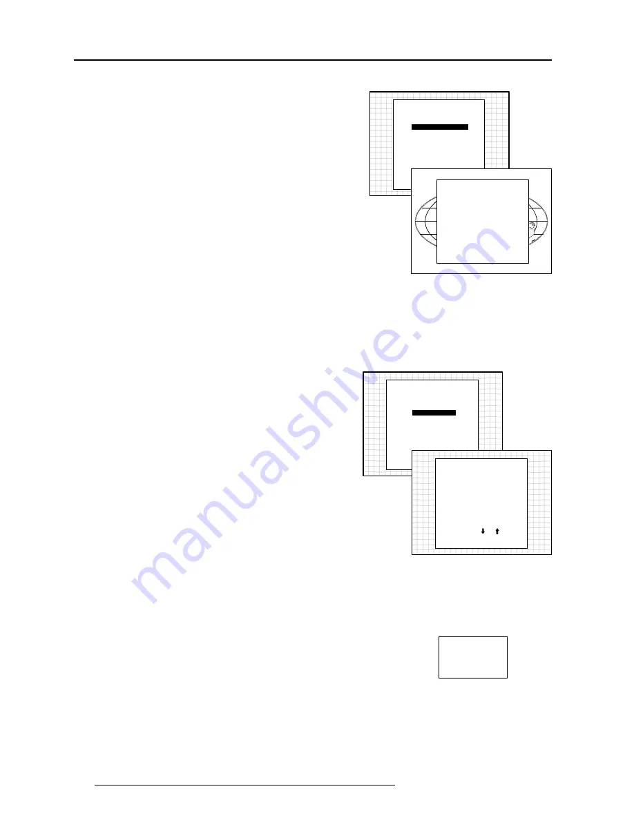
Projector Warm Up

Highlight 'Projector Warm Up' by pushing the control disk up or down
and press 

ENTER to select the projector warm up menu.

Select with       or

then <ENTER>

<EXIT> to return.

SERVICE MODE

G2 ADJUSTMENT

GAMMA CORRECTIONS

CRT RUN IN CYCLE

PROJECTOR WARM UP

CRT DRIVE MODE

MORE...

PROJECTOR WARM UP

OPTION : ON

A FULL WHITE PATTERN

WILL BE GENERATED FOR

20 MINUTES AT POWER UP

AFTER THIS PROCEDURE

THE PROJECTOR IS READY

TO PERFORM IN OPTIMUM

CONDITION

TOGGLE OPTION ON OR OFF

with <ENTER>

<EXIT> to return

The ON/OFF option can be toggled with the 

ENTER key.

When in the ON position (and the CRT run in cycle is OFF), the
projector can start up with a warm up period of 20 minutes.  During
the start up a warm up menu will displayed.  This menu offers the
possibility to skip the warm up periode anyway by pressing the EXIT
key and offers the possibility to adjust the horizontal and vertical
amplitude of the this white image with the control disk.   During this
warm up period, a full white image is shifted on the CRT faceplate to
avoid a burn in.
Every 30 seconds a text box will be displayed on another place on the
screen with the remaining time to go.
When EXIT is pressed during this warm up periode, the warm up
menu will be redisplayed with the remaining time indication.  Press
another time EXIT to interrupt the warm up cycle.
When the warm up option is OFF, when switching on the the
projector, it starts immediately with the projection of the selected
source.

CRT Drive Mode

The projector CRT's can be driven with the normal current (normal
mode), a lower current (economic mode) or with a higher current
(boost mode).
To change the drive mode, highlight 'CRT drive mode' by pushing the
control disk up or down and press ENTER to display the CRT drive
mode menu.

Select with       or

then <ENTER>

<EXIT> to return.

SERVICE MODE

G2 ADJUSTMENT

GAMMA CORRECTIONS

CRT RUN IN CYCLE

PROJECTOR WARM UP

CRT DRIVE MODE

MORE...

CRT DRIVE MODE

NORMAL

ECONOMIC

TEMPORARY BOOST

PERMANENT BOOST

WARNING : permanent

boost mode reduces the lifetime

of the CRT's !

Select with       or

then <ENTER>

<EXIT> to return.

To change the boost mode, push the control disk up or down to select
a display mode and press ENTER to select.

The following modes are available :

- normal

- economic : lower drive current to the CRT's, the lifetime of the CRT's

will enlarge but the light output will reduce.

- tempory boost : higher drive current to the CRT's, the lifetime of the

CRT's will shorten but the light output will be higher.  This situation
is tempory, when restarting the projector, the drive mode is auto-

matically set to normal.

- permanent boost : higher drive current to the CRT's, the lifetime of

the CRT's will shorten but the light output will be higher.  This setting
will be saved in the EEPROM.  When restarting the projector, it will
start up in boost mode.

A warning, permanent BOOST mode in use, will be displayed to
inform the user.
When text is on, this warning will be repeated every time a new
source is selected.

WARNING

PERMANENT
BOOST MODE
IN USE !

Содержание R9000972

Страница 1: ...GRAPHICS 1209s R9000972 R9000977 OWNER S MANUAL...

Страница 2: ...BARCO PROJECTION SYSTEMS Date 010797 Art No R5975628 GRAPHICS 1209s R9000972 R9000977 OWNER S MANUAL...

Страница 3: ...is subject to change without notice Produced by BARCO NV July 1997 All rights reserved Trademarks are the rights of their respective owners BARCO nv Projection Systems Noordlaan 5 B 8520 Kuurne Belgiu...

Страница 4: ...ing a VS05 switcher to the projector 3 6 Connecting an IR Remote Receiver to the projector 3 6 Controlling 4 1 Battery installation in the RCU 4 1 How to use your RCU 4 2 Projector Address 4 2 How to...

Страница 5: ...ock by block 7 3 Deletion of all blocks 7 3 Change password 7 4 Change Language 7 4 Run time 7 4 Set to midposition 7 5 Undo Midposition 7 5 Convergence Mid 7 5 Undo Convergence Mid position 7 5 Dynam...

Страница 6: ...dealer to switch over from 230Vac to 120 Vac or from 120Vac to 230 Vac If you are not sure of the type of AC power available consult your dealer or local power company 2 This product is equipped with...

Страница 7: ...nd refer servicing to qualified service personnel under the following conditions A When the power cord or plug is damaged or frayed B If liquid has been spilled into the equipment C If the product has...

Страница 8: ...eceiver for control signals transmitted from the RCU IR Remote Connector for remote input for hard wired remote control AC Power input RS232 OUT RS232 IN IR REMOTE 1 2 3 4 REMOTE IR RS232 OUT RS232 IN...

Страница 9: ...so Controlling for each picture function TEXT when adjusting one of the image controls during a meeting the displayed bar scale can be removed by press ing TEXT key first To re display the bar scale o...

Страница 10: ...d technician for power adaptation of the projector hm ON T 1 EO PROJECTOR MODE POWER MAINS PORT 2 S VIDEO 75 ohm ON OFF GREEN operational RED stand by 352 Switching On Off The projector is switched ON...

Страница 11: ...l be displayed Please use EXIT to leave this procedure b Start up without warm up period If the EXIT key is pressed the warm up period will be skipped and the projector is immediately ready for use Wa...

Страница 12: ...T2 S VIDEO LINE DOUBLER ON Highlight Picture Tuning and press ENTER Select Selected source and press ENTER Input selection with the RCU or the build in RCU press digit button 2 Depending on the priori...

Страница 13: ...git button 3 Connecting a RGB Analog source to port 4 5 RGB analog input terminals with separate H and V sync inputs with composite sync input or with sync signals on green automatic sync detection Al...

Страница 14: ...the build in RCU press digit button 8 Connecting a Component Video source with Tri level sync to port 4 5 Opion A component video R Y Y B Y with Tri level sync signals can be connected to the projecto...

Страница 15: ...R5975765 Connecting a VS05 switcher to the projector The VS05 can switch up to 5 Composite Video sources 3 S Video Sources and 1 RGB analog or component Video source to the projector In addition an a...

Страница 16: ...Remove the battery cover on the backside of the RCU by pushing the indicated handle a little to the bottom of the RCU Lift up the top side of the cover at the same time fig 1 Insert the new 9 V batte...

Страница 17: ...e built in RCU see paragraph The local keypad Projector Address a Software set up of the projector address See Change Projector Address in chapter Service Mode Every projector requires an individual a...

Страница 18: ...on With the digit buttons on the RCU it is possible to select input sources Video S Video RGsB or RGBS RG3sB or RGB3S When a valid and available source is selected there will be informa tion displayed...

Страница 19: ...cture Adjust the color saturation using the and buttons RCU A bar scale gives a visual indication on the screen of the current color setting while pressing on the above indicated keys If the bar scale...

Страница 20: ...orm the installation procedure see example of projected warning on the next page GUIDED Guided should be selected if the user intends to perform a complete alignment of the projected image All of the...

Страница 21: ...its Enter the digits with the numeric keys on the RCU Example 2 3 1 9 For each digit entered a X appears on the screen under the displayed text enter password When your password is correct you get acc...

Страница 22: ...t a path from below GUIDED RANDOM ACCESS INSTALLATION SERVICE IRIS Source 01 Select with or then ENTER EXIT to return ENTER continues to Setup Pattern Selection EXIT returns to Operational mode RANDOM...

Страница 23: ...NVERGENCE H SIZE V SIZE BLANKING LEFT BOTTOM RIGHT TOP V LINEARITY GREEN ONLY BLUE ON GREEN RED ON GREEN FOCUSING BLUE GREEN RED BLUE GREEN RED RED AND BLUE BLUE AND GREEN RED AND GREEN COLOR SELECT O...

Страница 24: ...ernal source connected to one of the inputs and the Genlocked Pattern is selected Internal Cross Hatch Pattern The Internal pattern menu will be displayed if the internal cross hatch pattern has been...

Страница 25: ...disk up or down to adjust the red cut off and push the control disk to the left or to the right to adjust the blue cut off Select custom Green cut off with the control disk and press enter to start t...

Страница 26: ...REQUENCY Clamp Tuning Highlight CLAMP TUNING by pushing the control disk up or down and press ENTER to toggle between NORMAL and RESTORA TION Select Normal for all standard sources and all sources wit...

Страница 27: ...ON active and OFF non active EXIT will return to the random access selection menu Select with or ENTER to accept EXIT to return PICTURE TUNING COLOR BALANCE SYNC FAST PORT2 S VIDEO LINE DOUBLER ON Co...

Страница 28: ...isk to the left or to the right to adjust the top focusing Adjust until the upper part of the image is sharp ENTER to return to the Green Focusing menu Bottom image focusing The same procedure has to...

Страница 29: ...eft Right Corrections Left Side Corrections Top Bottom Corrections Horizontal Size Vertical Linearity Vertical Size Blanking The convergence corrections are disabled during geometry correc tions The b...

Страница 30: ...RIGHT E W LEFT SIDE CORRECTION TOP BOTTOM N S H SIZE V LINEARITY V SIZE BLANKING ENTER will select green raster shift adjustment EXIT returns to random access adjustment mode menu Warning In order to...

Страница 31: ...OW SIDE KEYSTONE SEAGULL CORRECTION Warning Use this correction to adjust the right side of the image The warning Use this correction to adjust the right side of the image appears on the screen when s...

Страница 32: ...eft side correction insure that the side bow and keystone adjustments are done prior to these fine adjustments The following adjustments can be executed Left keystone Left bow Push the control disk up...

Страница 33: ...re straight To enter an alignment push the control disk up or down to highlight a function and press ENTER to activate this function Press EXIT to return TOP BOTTOM Select with or then ENTER EXIT to r...

Страница 34: ...ZE V LINEARITY V SIZE BLANKING TOP BOTTOM N S H CENTERLINE BOW H CENTERLINE SKEW TOP KEYSTONE TOP BOW BOTTOM KEYSTONE BOTTOM BOW SEAGULL CORRECTION Horizontal Size Adjustment Push the control disk up...

Страница 35: ...G V LINEARITY 70 Vertical Size Adjustment Push the control disk up or down to highlight V SIZE on the Geometry menu and then press ENTER ENTER will select vertical size adjustment EXIT returns to rand...

Страница 36: ...blanking Left blanking The following blanking corrections are possible top blanking bottom blanking left blanking right blanking Therefore if the internal pattern was selected this pattern remains on...

Страница 37: ...G COLOR SELECT ORBITING CONTR MODULATION SOFT EDGE CONVERGENCE Select with or then ENTER EXIT to return COARSE ADJUSTMENT RED ON GREEN BLUE ON GREEN FINE ADJUSTMENT GREEN ONLY RED ON GREEN BLUE ON GRE...

Страница 38: ...isk to make horizontal or vertical convergence adjustments in the selected zone and then press ENTER to move the box to another zone or EXIT to return to the Convergence menu ENTER toggles arrow keys...

Страница 39: ...ol disk up or down to select more ADJUSTMENT MODE Select with or then ENTER EXIT to return Select a path from below GUIDED RANDOM ACCESS INSTALLATION SERVICE IRIS source 1 Select with or then ENTER EX...

Страница 40: ...he control disk and press ENTER ENTER will select the highlighted item To copy the settings of a closed block to the block you are working on active block use the control disk to select a block All ex...

Страница 41: ...ock nr 1 DELETE BLOCK The selected block will be deleted ENTER to confirm EXIT to cancel Push the control disk up or down to select the desired adjustment block Press ENTER to delete the selected adju...

Страница 42: ...onfirm EXIT to return PASSWORD Enter new password 0 0 0 0 Password will be reprogrammed as xxxx ENTER to confirm EXIT to cancel CHANGE PASSWORD IDENTIFICATION COPY A BLOCK DELTE A BLOCK DELETE ALL BLO...

Страница 43: ...y readjusted When undo is pressed all settings are reset to the previous settings Convergence Mid Item is password protected Highlight convergence mid with the control disk and press ENTER to set all...

Страница 44: ...LTE A BLOCK DELETE ALL BLOCKS CHANGE PASSWORD CHANGE LANGUAGE RUN TIME SET TO MIDPOSITION CONVERGENCE MID DYNAMIC ASTIGMATISM MORE DYNAMIC ASTIGMATISM ON SELECTED SOURCE RED GREEN BLUE ON GENLOCKED PA...

Страница 45: ...the Service mode main menu Further description of the Gamma Corrections are given in the Installation manual Appendix C Select with or then ENTER EXIT to return SERVICE MODE WARNING RISK OF INCORRECT...

Страница 46: ...witching on the the projector it starts immediately with the projection of the selected source CRT Drive Mode The projector CRT s can be driven with the normal current normal mode a lower current econ...

Страница 47: ...warning will be dis playedwhenselectinganinputslot ofanRCVDSwheretheinputboard is missing WARNING source not available The input is a valid input but the source is not connected to the input terminals...

Страница 48: ...FAILURE IRIS commu nication error WAIT starting up IRIS Message during the start up of the IRIS Messagewilldisappearwhen the IRIS is ready to accept com mands CommunicationerrorbetweenIRIS 800 and th...

Страница 49: ...full use of mouse control pull down menus and dialog boxes Two main applications are available with this software remote control and transfering and receiving data of projector settings Remote Contro...

Страница 50: ...9827630 d 5 BNC to 5 BNC cable To connect an analog source to the BNC input of the projector Available lenght 60 cm order number R9828260 150 cm order number R9828261 5 m order number R9828262 15 m or...

Страница 51: ...MODULATION SOFT EDGE Orbiting Mode Toggle Switches The orbiting module is provided with a three pin connector for connection with the BARCO s BCl link option module used in multiple projector install...

Страница 52: ...biting mode set to OFF This alignment must be performed in case of a multiple projector installation with Master and Slave projectors in order to ensure a correct operation of the Orbiting for all pro...

Страница 53: ...n adjusting the horizontal and the vertical deviation the picture moves in corresponding direction allowing the set up of the deviation without orbiting operation EXIT to return SLAVE ORBITING CHANGE...

Страница 54: ...e data representing the values for all adjustments eg Convergence and Geometry in the projector for the source the block corresponds to The block header contains the basic characteristics of the sourc...

Страница 55: ...ment block is automatically stored Follow the steps below to create a second adjustment block for a source between 0 and 9 1 Select the source between 0 and 9 that the second adjustment block is to be...

Страница 56: ...1 5975628 BARCOGRAPHICS 1209s 010797 P RCU INPUT SOURCES 1 PROJECTOR RCVDS 2 3 4 5 6 1 2 3 5 6 7 8 9 10 INPUT SOURCES 7 P RCU INPUT SOURCES 1 PROJECTOR RCVDS 2 3 4 5 6 1 2 3 5 6 7 8 9 10 INPUT SOURCES...

Отзывы: