3. Physical installation
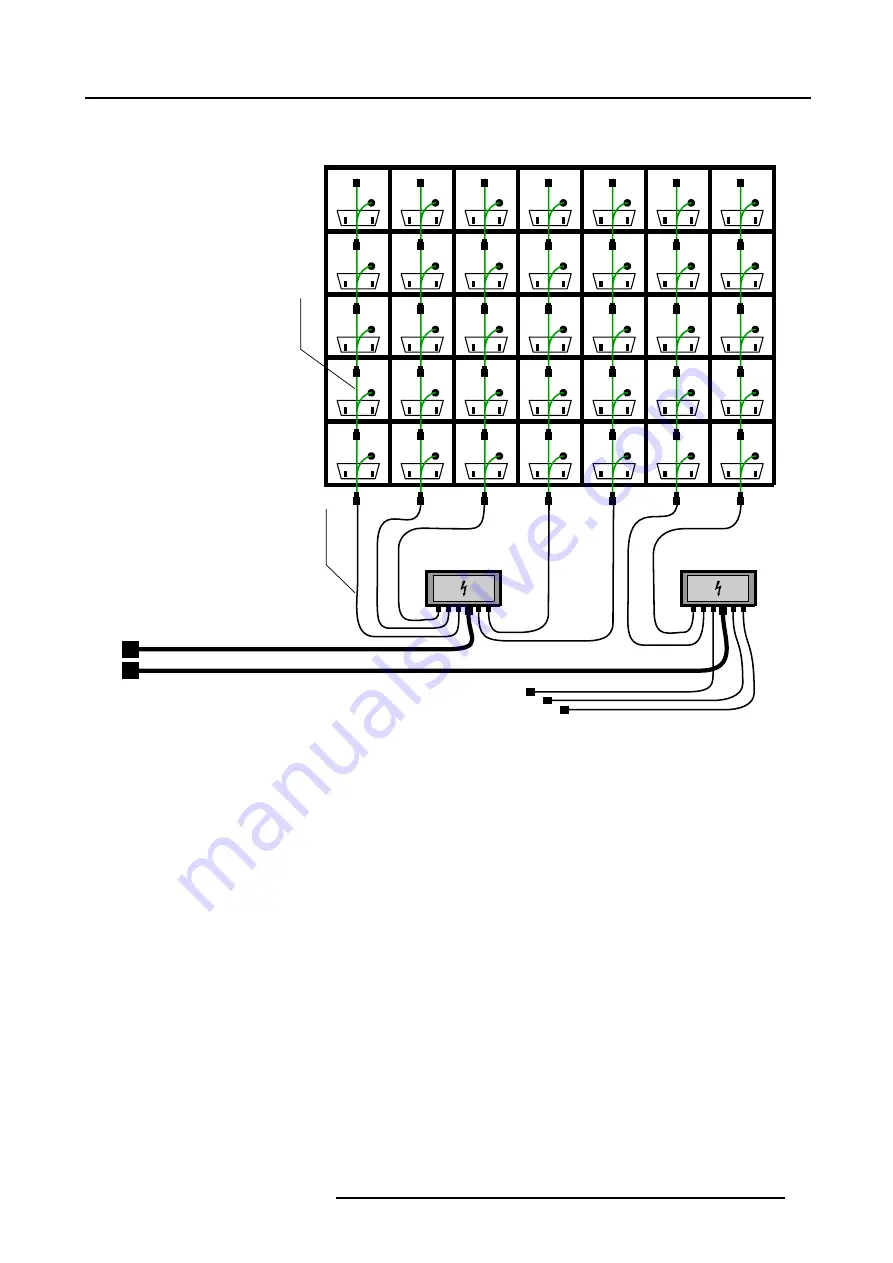
Example of power cabling with a ILite Mono Phase Power Box
ILite display rear view
(A)
Power
source
cable
(C)
Power
linking
cable
(D)
Mono Phase
Power Box
(B)
Mono Phase
Power Box
(B)
POWER
DATA
POWER
DATA
POWER
DATA
POWER
DATA
POWER
DATA
POWER
DATA
POWER
DATA
POWER
DATA
POWER
DATA
POWER
DATA
POWER
DATA
POWER
DATA
POWER
DATA
POWER
DATA
POWER
DATA
POWER
DATA
POWER
DATA
POWER
DATA
POWER
DATA
POWER
DATA
POWER
DATA
POWER
DATA
POWER
DATA
POWER
DATA
POWER
DATA
POWER
DATA
POWER
DATA
POWER
DATA
POWER
DATA
POWER
DATA
POWER
DATA
POWER
DATA
POWER
DATA
POWER
DATA
POWER
DATA
Image 3-21
A
ILite Display rear view.
B
ILite Mono Phase Power Box.
C
Output cable.
D
Power linking cable.
3.6.2.2
Connections with a Custom Power Box
Necessary parts
•
Custom Power Box.
•
Multi power cables.
•
ILite Spider connector with Spider support bracket.
•
Power linking cables.
•
Cable ties.
Power connections
1. Install the Custom Power Box on a safe location near by the ILite display.
2. Connect a multi power cable, with an adapted length, with one of the multi pole connectors on the Custom Power Box. (im-
3. Connect the other side of the multi power cable with an ILite Spider connector near by the ILite display. Use the Spider support
bracket to attach the Spider connector to the back side of the display wall. (image 3-23)
4. Start creating power branches by connecting the output cables of the ILite Spider connector with the power linking cable of the
lowest tile in a column of maximum six.
R5976522 FIXED ILITE DISPLAY 05042004
31
Содержание ILite Series
Страница 1: ...MEDIA FIXED ILITE DISPLAY INSTALLATION MANUAL For I6 I6 XP I8 I10 I12 tiles 05042004 R5976522 02 ...
Страница 4: ......
Страница 6: ...Table of contents 2 R5976522 FIXED ILITE DISPLAY 05042004 ...
Страница 10: ...1 Safety 6 R5976522 FIXED ILITE DISPLAY 05042004 ...
Страница 42: ...4 Servicing 38 R5976522 FIXED ILITE DISPLAY 05042004 ...


