


R5909934 /00
E2 Lite and EC-40
83
6.13 Configuration Menu > Adjustment > Input
Configuration
General
In the Input configuration menu users can assign input connectors to inputs and adjust parameters to match
the incoming signal format and timing parameters.
Input Card arrangement
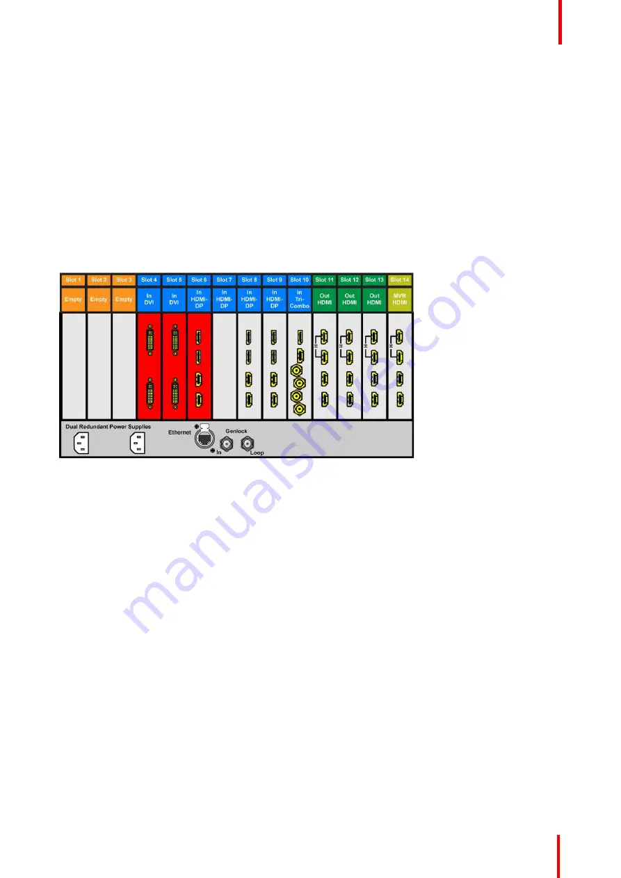
On the E2 Lite model, the input cards occupy slots 3 through 10 and are right justified to slot 10.
If there is an empty input slot between two input slots, all input cards to the left of the empty slot are marked
with red. Red indicates that although the cards will operate properly, inputs from these cards will not be
available at the Multiviewer.
Image 6-14: E2 Lite with an empty input-card slot
If the card in the slot is wrong type (e.g. output card in input slot, or vice versa) then the slot in the diagram will
be greyed out.
Input Connector Grouping
The reason for connector grouping is that in order to accommodate higher resolutions with no loss of quality
bandwidth has to be added to the signalpath. By combining connectors a higher resolution all the way up to
4K@60Hz with progressive scan can be added with its full color space 4:4:4.
There several rules that applies when defining an input configuration:
1.
Every Input connector can only be assigned to one input.
2.
Input types in the same configuration must be of the same type and in the same slot or in adjacent slots.
For example, cannot have a HDMI connector and an SDI connector in the same input configuration.
Exception to this is the HDMI and DVI connectors.
3.
An input can be defined from one, two or four connectors.
4.
A grouped connector is still ONE input.
5.
Once an input connector is assigned to an input that already contains another one.
6.
Maximum of 4 connectors can be assigned to a layer, Input.
7.
Maximum of 128 input configurations can be assigned.
Содержание Event Master E2 Lite
Страница 1: ...ENABLING BRIGHT OUTCOMES User s Guide E2 Lite and EC 40...
Страница 10: ...R5909934 00 E2 Lite and EC 40 10...
Страница 14: ...R5909934 00 E2 Lite and EC 40 14 Introduction...
Страница 18: ...R5909934 00 E2 Lite and EC 40 18 Safety...
Страница 32: ...R5909934 00 E2 Lite and EC 40 32 General...
Страница 46: ...R5909934 00 E2 Lite and EC 40 46 Hardware orientation...
Страница 168: ...R5909934 00 E2 Lite and EC 40 168 EM GUI orientation...
Страница 208: ...R5909934 00 E2 Lite and EC 40 208 Controller Orientation...
Страница 214: ...R5909934 00 E2 Lite and EC 40 214 Controller Configuration...
Страница 220: ...R5909934 00 E2 Lite and EC 40 220 Controller Operation...
Страница 226: ...R5909934 00 E2 Lite and EC 40 226 13 2 Process Overview Flow chart Image 13 2 E2 Lite Maintenance...
Страница 284: ...R5909934 00 E2 Lite and EC 40 284 E2 Lite Maintenance...
Страница 289: ...289 R5909934 00 E2 Lite and EC 40 Environmental Information 15...
Страница 300: ...R5909934 00 E2 Lite and EC 40 300 Specifications...
Страница 316: ...R5909934 00 E2 Lite and EC 40 316 Remote Control Protocol...
Страница 317: ...317 R5909934 00 E2 Lite and EC 40 Troubleshooting C...
Страница 320: ...R5909934 00 E2 Lite and EC 40 320 Troubleshooting...
Страница 329: ...R5909934 00 E2 Lite and EC 40 329 Index...


