118
DCS-200 • User’s Guide
^K==péÉÅáÑáÅ~íáçåë
Pinouts
máåçìíë=
The following topics are discussed in this section:
•
•
•
•
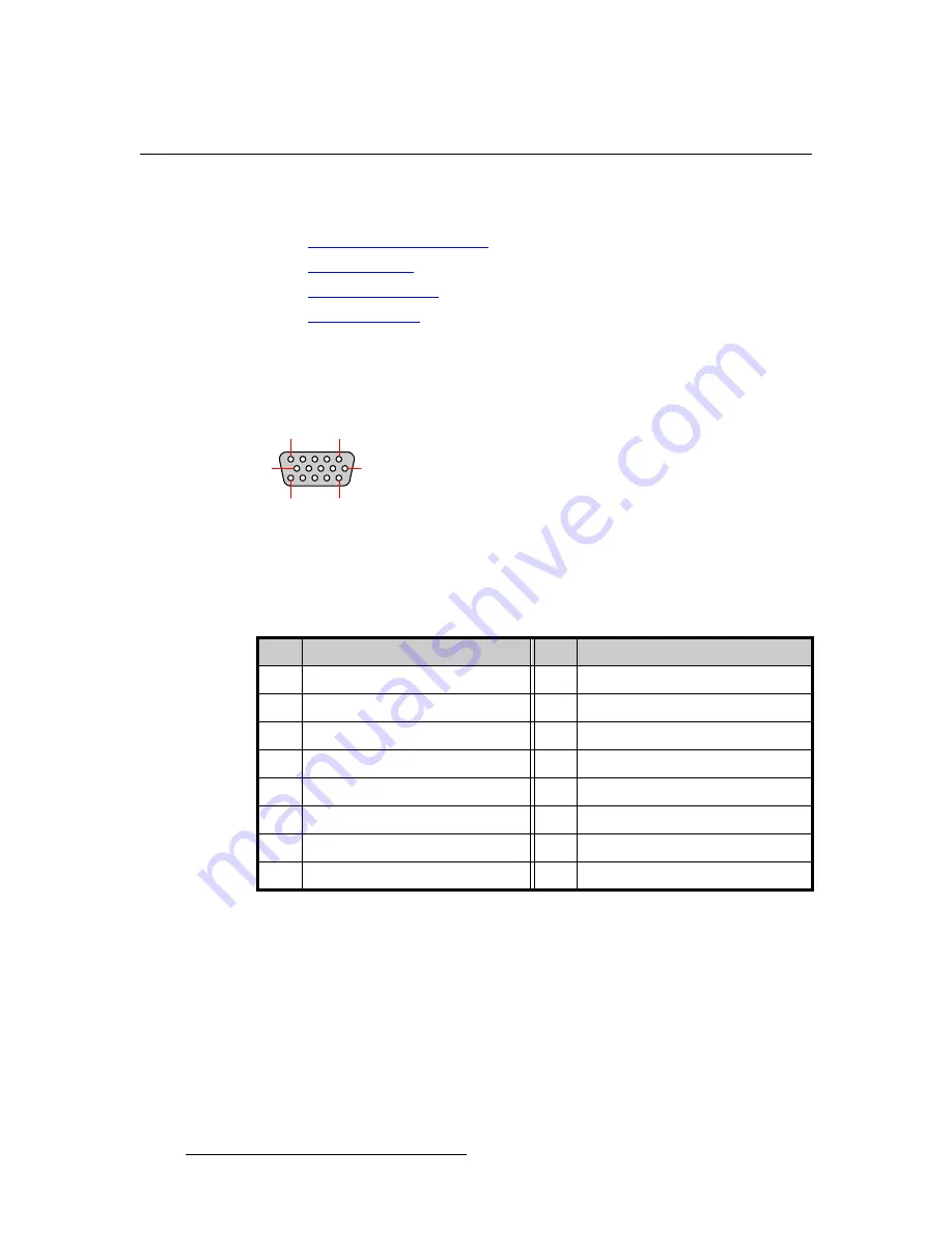
^å~äçÖ=NRJéáå=a=`çååÉÅíçê
The figure below illustrates the analog 15-pin D connector:
Figure A-1.
Analog 15-pin D connector, chassis view
The table below lists Analog 15-pin D connector pinouts.
Table A-6.
Analog 15-pin D Connector Pinouts
Pin
Signal
Pin
Signal
1
Red
9
+5V DDC Power
2
Green
10
GND
3
Blue
11
4
12
DDC Data
5
13
H Sync or C Sync
6
Red return
14
V Sync
7
Green return
15
DDC Clock
8
Blue return
10
6
5
1
15
11
Содержание DCS-200
Страница 1: ...r d a pJOMM Manual 26 0604010 00 Revision 00...
Страница 114: ...114 DCS 200 User s Guide 6 Upgrading Software Ethernet Upgrade Method...
Страница 126: ...126 DCS 200 User s Guide K p Format Table...
Страница 158: ...158 DCS 200 User s Guide _K o Remote Commands...


