13. Projector control
Image 13-28
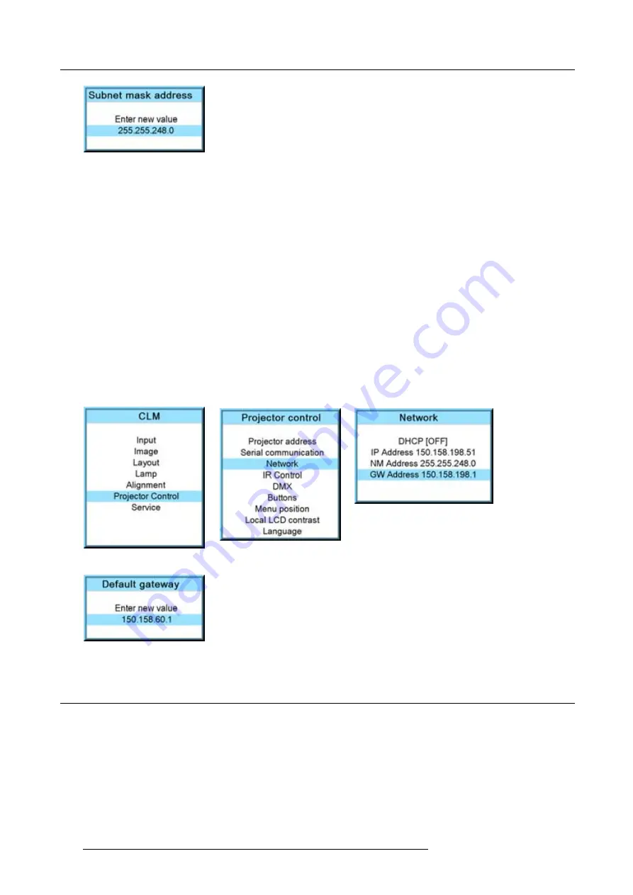
13.4.5 Default Gateway set up
How to set up?
1. Press
MENU
to activate the menus.
2. Use the
▲
or
▼
key to select
Projector control
and press
ENTER
.
3. Use the
▲
or
▼
key to select
Network
and press
ENTER
.
The Ethernet menu opens.
4. Use the
▲
or
▼
key to select
Default Gateway
and press
ENTER
to select.
Note:
An address contains 4 octets with a maximum value of 255.
Set the default gateway to the IP-address of the router (MUST be on the local subnet!). If there is no router on the projector’s
local subnet then just set this
fi
eld to any IP-address on the subnet.
5. Use the
▲
or
▼
key to select the desired digit and press
◄
or
►
key to select the next digit in the address.
Or,
enter the value with the digit keys on the remote control or local keypad. The next digit in the address will be selected automati-
cally. (image 13-29, image 13-30, image 13-31, image 13-32)
Note:
This must NOT be 0.0.0.0
6. Press
EXIT
to return.
Image 13-29
Image 13-30
Image 13-31
Image 13-32
13.5 IR control switching
What can be done?
Each IR receiver inside the projector can be activated or deactivated. When an IR receiver is deactivated, no IR signal send to this
IR receiver will be processed. When entering an Activation code with the remote control all IR receivers can be activated at the
same time.
How to switch
1. Press
MENU
to activate the menus.
2. Use the
▲
or
▼
key to select
Projector control
and press
ENTER
.
3. Use the
▲
or
▼
key to select
IR Control
and press
ENTER
.
144
R59770021 CLM R10+ 11/10/2010
Содержание CLM R10+
Страница 1: ...CLM R10 Users manual R9050100 R90501001 R90501005 R59770021 11 11 10 2010 ...
Страница 14: ...1 Safety 10 R59770021 CLM R10 11 10 2010 ...
Страница 22: ...2 General 18 R59770021 CLM R10 11 10 2010 ...
Страница 36: ...3 Physical installation 32 R59770021 CLM R10 11 10 2010 ...
Страница 41: ...4 Stacking CLM projectors Zoom Image 4 9 Zoom adjustment R59770021 CLM R10 11 10 2010 37 ...
Страница 42: ...4 Stacking CLM projectors 38 R59770021 CLM R10 11 10 2010 ...
Страница 50: ...5 Connections 46 R59770021 CLM R10 11 10 2010 ...
Страница 66: ...7 Start up of the Adjustment mode 62 R59770021 CLM R10 11 10 2010 ...
Страница 75: ...8 Input menu Image 8 26 Image 8 27 Image 8 28 R59770021 CLM R10 11 10 2010 71 ...
Страница 76: ...8 Input menu 72 R59770021 CLM R10 11 10 2010 ...
Страница 102: ...9 Image menu 98 R59770021 CLM R10 11 10 2010 ...
Страница 116: ...10 Layout menu Image 10 61 Image 10 62 Image 10 63 Image 10 64 112 R59770021 CLM R10 11 10 2010 ...
Страница 169: ...14 Service menu Image 14 55 Image 14 56 Image 14 57 R59770021 CLM R10 11 10 2010 165 ...
Страница 170: ...14 Service menu 166 R59770021 CLM R10 11 10 2010 ...
Страница 183: ...16 Servicing Image 16 15 Top up reservoir 2 cm Image 16 16 Pressurize circuit R59770021 CLM R10 11 10 2010 179 ...
Страница 184: ...16 Servicing 180 R59770021 CLM R10 11 10 2010 ...
Страница 194: ...17 Projector covers removal and installation 190 R59770021 CLM R10 11 10 2010 ...
Страница 202: ...C DMX Chart 198 R59770021 CLM R10 11 10 2010 ...
Страница 212: ...E Troubleshooting 208 R59770021 CLM R10 11 10 2010 ...
Страница 217: ...F Mounting optional Carry handle 1 2 3 1 4 5 Image F 7 Image F 8 R59770021 CLM R10 11 10 2010 213 ...
Страница 218: ...F Mounting optional Carry handle 214 R59770021 CLM R10 11 10 2010 ...
Страница 220: ...G Order info 216 R59770021 CLM R10 11 10 2010 ...
Страница 228: ...Index 224 R59770021 CLM R10 11 10 2010 ...


