background image

9. Image menu

Level 1

Level 2

Level 3

Level 4

Vertical start

Advanced settings

Clamp delay

Clamp width

Field polarity

Film mode detection

Image

fi

le services

Manual load

Delete

Delete all

Rename

Copy

Options

Load

fi

le

Save custom settings

9.2

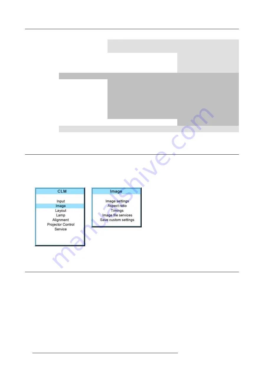
How to select the image adjustments?

Start up

1. Use the

or

key to select

Image

.

2. Press

ENTER

to select.

The

Image

menu opens. (image 9-1image 9-2)

Image 9-1

Image 9-2

9.3

Image Settings

Overview

Contrast

Brightness

Saturation

Tint (hue)

Phase

Sharpness

Noise reduction

Color temperature

Input balance

74

R59770021 CLM R10+ 11/10/2010

Содержание CLM R10+ R90501001

Страница 1: ...CLM R10 Users manual R9050100 R90501001 R90501005 R59770021 11 11 10 2010...

Страница 2: ...Barco nv Events Noordlaan 5 B 8520 Kuurne Phone 32 56 36 82 11 Fax 32 56 36 88 24 E mail sales events barco com Visit us at the web www barco com Printed in Belgium...

Страница 3: ...and Compensation Barco provides a guarantee relating to perfect manufacturing as part of the legally stipulated terms of guarantee On receipt the purchaser must immediately inspect all delivered good...

Страница 4: ...ing and mailing a CD will be charged Disposal Information This equipment has required the extraction and use of natural resources for its production It may contain hazardous substances for health and...

Страница 5: ...rs 35 5 Connections 39 5 1 Power connection 39 5 2 Input source connections 41 5 3 Communication connections 42 6 Getting started 47 6 1 RCU Local keypad 47 6 2 Terminology overview 47 6 3 Operating t...

Страница 6: ...0 9 5 4 Advanced setting brilliant color look 91 9 6 Image files services 92 9 6 1 Files and file manipulations 92 9 6 2 Manual Load file 93 9 6 3 Delete file 93 9 6 4 Delete all custom files 94 9 6 5...

Страница 7: ...ing 144 13 6 DMX 145 13 6 1 DMX address 145 13 6 2 DMX universe 146 13 6 3 DMX monitor 147 13 6 4 DMX mode 148 13 6 5 Art Net Activation 149 13 7 Buttons 149 13 7 1 APA button 149 13 7 2 Shortcut keys...

Страница 8: ...mensions 191 A 1 Dimensions of the CLM R10 191 B Standard Source Files 193 B 1 Table overview 193 C DMX Chart 195 C 1 CLM control channel mapping Full mode 195 C 2 CLM control channel mapping Basic mo...

Страница 9: ...and having access to live parts Safety standards also impose limits to the internal and external temperature rises radiation levels mechanical stability and strength enclosure construction and protect...

Страница 10: ...allation procedures Warning high intensity light beam NEVER look into the lens High luminance could result in damage to the eye Before attempting to remove any of the projector s covers you must turn...

Страница 11: ...pply immediately Do not operate the projector again until it has been checked by qualified service technicians Consult a professional structural engineer prior to suspending the ceiling mount from a s...

Страница 12: ...ive work by a qualified technician to restore the product to normal operation If the product has been dropped or the cabinet has been damaged If the product exhibits a distinct change in performance i...

Страница 13: ...t the four lock handles on each flight case are in good working order and locked securely When stacked make sure the wheels of the upper flight case are precisely positioned in the stacking dishes of...

Страница 14: ...1 Safety 10 R59770021 CLM R10 11 10 2010...

Страница 15: ...R9050100 and R90501001 requires 100 120 200 240V 12 8A 50 60Hz One Barco CLM R10 order number R90501005 requires 100 120 200 240V 16 8A 50 60Hz Clean air environment A projector must always be mounte...

Страница 16: ...your local screen supplier What image size How big should the image be The projector is designed for projecting an image size minimum 2 meter 6 6 ft to maximum 10 meter 32 8 ft depending on the ambien...

Страница 17: ...As soon as the projector is unpacked inspect for any damage that may have occurred in transit Save all packing material until the inspection is completed If damaged is found file claim with carrier i...

Страница 18: ...configurations are 1 Front Table F T 2 Front Ceiling F C 3 Rear Table R T 4 Rear Ceiling R C For a ceiling mounted configuration the optional carry handle kit is required Front projection F C AUDIENC...

Страница 19: ...the position in any installation Formula to calculate the distance CD for On Axis projection CD SH 2 B A Shift range The lens can be shifted with respect to the DMD P which result in a shifted image...

Страница 20: ...slightly decline of image quality depending on the used lens and the zoom position of the used lens Furthermore shifting too much in both directions will result in a blurred image corner Horizontal a...

Страница 21: ...simultaneously Even when the configurations are connected via different ways Projector Toolset is only available in a download version no CD can be ordered Where to find the download file s The progr...

Страница 22: ...2 General 18 R59770021 CLM R10 11 10 2010...

Страница 23: ...ge 39 5 Connect your source to the appropriate input module see Input source connections page 41 6 Switch ON the projector see procedure Switching on page 49 7 Select the input slot at which your sour...

Страница 24: ...stall the batteries in the remote control 1 Push the battery cover tab with the fingernail a little backwards 1 and pull at the same time the cover upwards 2 image 3 2 2 Insert the two AA size batteri...

Страница 25: ...daptor installation Install the rugged case before installing the XLR adaptor Vice versa remove the XLR adaptor before removing the rugged case from the RCU Necessary tools 5 mm flat screw driver Nece...

Страница 26: ...ired b RCU wired mini jack Backlight illuminates continuously when wire is connected Infra red disabled c RCU with rugged case not wired d RCU with rugged case wired mini jack Backlight illuminates co...

Страница 27: ...Lens selection Lens formulas Lens formulas 3 2 1 Available lenses Overview First series lenses Image 3 9 R9849870 CLD zoom lens 1 2 1 6 1 Image 3 10 R9861100 CLD zoom lens 1 6 2 4 1 Image 3 11 R98498...

Страница 28: ...elect the right lens for your application 1 Determine the required screen width SW 2 Determine the position of the projector in the projection room with regard to the screen and measure the projector...

Страница 29: ...projector Neglecting this can damage the Lens Holder and Prism 3 2 4 Lens formulas Formulas Lens Throw ratio for CLM Metric formulas meter Inch formulas inch CLD 1 2 1 5 1 1 25 1 58 PDmin 1 25 x SW 0...

Страница 30: ...mps Before the projector can be suspended the optional carry handle must be mounted on the projector For more information about the optional carry handle see Mounting optional Carry handle page 209 CA...

Страница 31: ...ing the measured distance and secure this position by fastening the nut completely Ensure that the rigging points are symmetrically lined up so that the projector will hang in balance If necessary mov...

Страница 32: ...3 Physical installation Image 3 20 Mount rigging points X mm Image 3 21 x mm A B Image 3 22 Set up truss width 28 R59770021 CLM R10 11 10 2010...

Страница 33: ...3 Physical installation Image 3 23 Mounting rigging clamps Image 3 24 Opening clamps R59770021 CLM R10 11 10 2010 29...

Страница 34: ...3 25 Mounting to truss Image 3 26 Security cable CAUTION Always mount the safety cable when suspending the projector 3 5 Alignment of a ceiling mounted CLM projector Necessary tools Spanner 17 mm 30...

Страница 35: ...of the screen 2 Project one of the internal hatch patterns on the screen 3 Adjust the height of the rigging clamps with respect to the projector until the projected hatch pattern is rectangle shaped a...

Страница 36: ...3 Physical installation 32 R59770021 CLM R10 11 10 2010...

Страница 37: ...s on top of each other Ensure that all three interlocking pins A match with their corresponding interlocking sockets B image 4 1 Tip In case of stacking projectors for a ceiling mount configuration fi...

Страница 38: ...jectors A B C D Image 4 2 Close the interlocking Image 4 3 Ceiling mounted stacked projectors How to open an interlocking adapter 1 Open an interlocking adapter as illustrated image 4 4 34 R59770021 C...

Страница 39: ...h pattern is most symmetric with the reference hatch pattern image 4 5 Tip You can increase leverage by using a screw driver in the holes of the adjustment ring 4 If necessary adjust the inclination o...

Страница 40: ...acking CLM projectors Rotation Image 4 5 Rotation adjustment Inclination Image 4 6 Inclination adjustment Skew Q Image 4 7 Skew adjustment Shift Image 4 8 Shift adjustment 36 R59770021 CLM R10 11 10 2...

Страница 41: ...4 Stacking CLM projectors Zoom Image 4 9 Zoom adjustment R59770021 CLM R10 11 10 2010 37...

Страница 42: ...4 Stacking CLM projectors 38 R59770021 CLM R10 11 10 2010...

Страница 43: ...to connect with the local power net 1 Ensure that the power switch S stands in the 0 OFF position 2 Connect the power cord with the power input socket of the projector P 3 Secure the power plug by lo...

Страница 44: ...own the projector first switch off the power switch and then unplug the power cord Fuses The projector is protected with an automatic circuit breaker of 20 A which is built in into the power switch Po...

Страница 45: ...e that the slot numbering is done from top to bottom So the uppermost slot is slot number 1 the second is slot number 2 All input modules have two status LED s The green LED lights up if the input mod...

Страница 46: ...display for diagnostic code Projector status The projector status LED A lights up green while in operation The same LED lights up red when the projector is switched to standby Besides the projector s...

Страница 47: ...ctive RS232 RS422 loop through output port Whenever the projector has no power a passive loop through is created from the RS232 RS422 input port to the RS232 RS422 output port So the following project...

Страница 48: ...he Ethernet port E on the communication interface Once connected to the LAN users are capable of accessing the projector from any location inside or outside if allowed their company network using the...

Страница 49: ...e used You can use the DMX input port G to connect a DMX device to the CLM projector This way you can control the CLM projector from that DMX device The DMX output port G can be connected with the nex...

Страница 50: ...5 Connections 46 R59770021 CLM R10 11 10 2010...

Страница 51: ...e controlled by the local keypad or by the remote control unit Location of the local keypad The local keypad is located on the input side of the projector Remote control functions This remote control...

Страница 52: ...button between 0 and 9 5 LENS Direct access key to the lens adjustment menus Toggling this key will change the projected pattern 6 PAUSE To stop projection for a short time press PAUSE The image disap...

Страница 53: ...he local LCD panel 17 ENTER Key to confirm an adjustment or selection in the adjustment mode 18 Cursor keys To make menu selections when in the adjustment mode 19 EXIT Key to go one menu stage higher...

Страница 54: ...uces an error message When the DMD temperature is too low Lower than 0 C warning is displayed on the LCD panel and yellow warning LED is on Both remains until the temperature is above 10 C Between 0 C...

Страница 55: ...6 4 Using the RCU Pointing to the reflective screen 1 Point the front of the RCU to the reflective screen surface image 6 4 F 1 F 2 F 3 F 4 F 5 A D J E X I T E N T E R P A U S E P H A S E T E X T S H...

Страница 56: ...Quick Lens Adjustment Quick picture in picture Quick layout selection with Rigging key Quick language selection 6 5 1 Text boxes ON or OFF Text toggle function The on screen text boxes can be switche...

Страница 57: ...nother pattern Different patterns are available 6 5 2 2 Direct Lens Adjustment RCU Lens adjustment buttons on the Remote Control On the Remote Control four buttons with double action are provided allo...

Страница 58: ...igits to jump to a new layout When Rigging is pressed an overview of the possible layouts with a sequence number is given on the local LCD panel That sequence number is the number that should be press...

Страница 59: ...igured as an auto align of the projected source or as an auto image button which calls a choice menu Within this choice menu the user can execute an auto align of the image an auto contrast brightness...

Страница 60: ...it key Otherwise the address is not entered in the remote control 6 7 2 Controlling the projector Projector address Address installed in the projector to be individually controlled Common address Proj...

Страница 61: ...on until the main window is activated and then select the desired source with the digit keys 6 9 Controlling the Projector Picture Controls When an image control is pressed a text box with a bar scale...

Страница 62: ...ause key Select a source number The Stand by Key When the Stand by key is pressed the image projection is stopped and the projector goes to stand by This situation is used when a projection stop is pl...

Страница 63: ...ontrol contains the accessibility settings of the projector such as address and communication setup Service contains information about how the projector is performing This information will be useful w...

Страница 64: ...nd of the progress bar indicates the adjustment ranges Image 7 2 While a bar scale is displayed it is also possible to enter the desired value directly with the digit keys Therefore press ENTER The me...

Страница 65: ...s selected even when selecting other menus When leaving the adjustment mode the selected test pattern is cleared and the normal image is displayed again 7 7 Menu memory Overview Each menu with sub men...

Страница 66: ...7 Start up of the Adjustment mode 62 R59770021 CLM R10 11 10 2010...

Страница 67: ...k blue Shutdown Off On Shutdown time 8 2 Slot module type Overview About Input Setup Input configuration 8 2 1 About Input Setup Overview Each input module must be configured before these module can b...

Страница 68: ...dow is different for each module type 5 Use the or key to select desired mode for the selected slot image 8 1 image 8 2 image 8 3 image 8 4 Image 8 1 Image 8 2 Image 8 3 Image 8 4 Possible results Inp...

Страница 69: ...ation For shorter cables adjust between 13 and 15 least equalization Advanced settings for 5 cable input For RGB with separate sync or YUV with separate sync the sync level can be toggled between Anal...

Страница 70: ...select Manual lock and press ENTER to toggle between On and Off Manual lock on locking is done on the indicated vertical frequency which can be changed by the user Manual lock off locking is done on...

Страница 71: ...ted with software packages older than package 1 5 6 the Genlock function will be grayed out If you want to use this genlock function a new custom file must be created starting from the standard file C...

Страница 72: ...cted UXGA 4 3 1600x1200 4 3 1600x1200 part of the image displayed image scroll possible How to toggle to native resolution 1 Press MENU to activate the menus 2 Use the or key to select Input and press...

Страница 73: ...ource switching effect is activated Fade Fade in fade out effect is activated Transition time can be set up 5 Use the or key to select Effect time and press ENTER 6 Enter the desired time with the dig...

Страница 74: ...R to toggle between On and Off image 8 23 image 8 24 im age 8 25 Image 8 23 Image 8 24 Image 8 25 8 7 3 Shutdown retarding time Only accessible when Shutdown is set to On How to set the retarding time...

Страница 75: ...8 Input menu Image 8 26 Image 8 27 Image 8 28 R59770021 CLM R10 11 10 2010 71...

Страница 76: ...8 Input menu 72 R59770021 CLM R10 11 10 2010...

Страница 77: ...1 Level 2 Level 3 Level 4 Image Image settings Contrast Brightness Saturation Tint Phase Sharpness Noise reduction Color temperature Projector white Computer 9300K Video 6500K Film 5400K Broadcast 320...

Страница 78: ...ll Rename Copy Options Load file Save custom settings 9 2 How to select the image adjustments Start up 1 Use the or key to select Image 2 Press ENTER to select The Image menu opens image 9 1 image 9 2...

Страница 79: ...he higher the value the higher the contrast image 9 3 image 9 4 image 9 5 image 9 6 Image 9 3 Image 9 4 Image 9 5 Image 9 6 9 3 2 Brightness About Brightness The Brightness function is used to adjust...

Страница 80: ...menus 2 Use the or key to select Image and press ENTER 3 Use the or key to select Image settings and press ENTER 4 Use the or key to select Saturation and press ENTER The Saturation progress bar appe...

Страница 81: ...elect Tint and press ENTER The Tint progress bar appears 5 Use or to change the tint The higher the value the higher the tint image 9 15 image 9 16 image 9 17 image 9 18 Image 9 15 Image 9 16 Image 9...

Страница 82: ...n pixel off pattern For example shut down screen of a PC Image 9 20 Image 9 21 Image 9 22 Image 9 23 9 3 6 Sharpness About Sharpness The sharpness function is used to adjust the image sharpness of vid...

Страница 83: ...se reduction The higher the value the higher the noise reduction image 9 28 image 9 29 image 9 30 image 9 31 Image 9 28 Image 9 29 Image 9 30 Image 9 31 9 3 8 Color temperature What can be done The co...

Страница 84: ...racking How to select 1 Press MENU to activate the menus 2 Use the or key to select Image and press ENTER 3 Use the or key to select Image settings and press ENTER 4 Use the or key to select Color tem...

Страница 85: ...n transporting signals there is always a risk of deterioration of the information contained in the signals In case of information contained in the amplitude of the signals which is the case of data co...

Страница 86: ...fluous information i2 video information Image 9 43 One can conclude here that a good data conversion can only be met by using three previously input balanced color signals The objective of input balan...

Страница 87: ...min to max is indicated by the apparition of bright spots also called digital noise An alternative to a full screen White black pattern is the standard gray scale pattern the white bar will be used f...

Страница 88: ...lect Input balance and press ENTER 6 Do you want to use an internally generated test pattern If yes Use the or key to select Test pattern and press ENTER to toggle between on and off If no select a wh...

Страница 89: ...Description 4 3 Standard television format 16 9 Wide screen television format anamorphic format 5 4 Workstation format 2 35 Film format 1 88 1 78 Wide screen television format anamorphic format Custom...

Страница 90: ...enus 2 Use the or key to select Image and press ENTER 3 Use the or key to select Aspect ratio and press ENTER The aspect ratio menu will be displayed 4 Use the or key to select the desired aspect rati...

Страница 91: ...ctive vertical lines number of horizontal lines determining the height of the projected image this value is normally given in the specification of the source If not adjust until full image height is d...

Страница 92: ...edge Trailinging edge Image 9 66 Field polarity The field polarity function is used for interlaced images Both rasters of the image could be shifted in a wrong way double lines are visible in the imag...

Страница 93: ...mage 9 70 How to change the field polarity 1 Press MENU to activate the menus 2 Use the or key to select Image and press ENTER 3 Use the or key to select Advanced settings and press ENTER The Advanced...

Страница 94: ...ipment can unravel the 3 2 sequence to allow frame by frame treatment and subsequently re compose 3 2 The 3 2 sequence repeats every five video frames and four film frames the latter identified as A D...

Страница 95: ...lights Some predefined looks optimized for either computer images or video images are selectable with the brilliant color look function Select data when projecting computer images Select Vid 1 or Vid...

Страница 96: ...e loaded and saved for future use When there is a little difference the file can also be loaded and then edited until the source specs are reached VESA standards and video standards are pre programmed...

Страница 97: ...menu If yes Select Filter and use till FIT is on the menu If no Select Filter and use till ALL is on the menu 6 Use the or key to select the appropriate file While scrolling over the files a preview...

Страница 98: ...r key to select Image and press ENTER 3 Use the or key to select File services and press ENTER The File service menu is displayed 4 Use the or key to select Delete all and press ENTER A delete all con...

Страница 99: ...6 Press ENTER to select The rename window opens The first character is selected 7 Use the or key to change the selected character Use the or key to selected another character Note Digits can be entere...

Страница 100: ...ions How to set the options 1 Press MENU to activate the menus 2 Use the or key to select Image and press ENTER 3 Use the or key to select Image services and press ENTER The Image service menu is disp...

Страница 101: ...it would be done when the projector was switched to standby How to save 1 Press MENU to activate the menus 2 Use the or key to select Image and press ENTER 3 Use the or key to select Save custom setti...

Страница 102: ...9 Image menu 98 R59770021 CLM R10 11 10 2010...

Страница 103: ...vices Load Main full screen PIP top right Split top bottom Rename Delete Copy Save as Zoom Focus Same for each layout yes no 10 2 Main window Overview Source selection Size adjustment Position adjustm...

Страница 104: ...MENU to activate the menus 2 Use the or key to select Layout and press ENTER 3 Use the or key to select Main Window and press ENTER The main window opens 4 Use the or key to select Source and press E...

Страница 105: ...r key to select Main Window and press ENTER The main window opens 4 Use the or key to select Size and press ENTER The size adjustment window opens image 10 8 image 10 9 image 10 10 5 Toggle with ENTER...

Страница 106: ...dow opens image 10 13 image 10 14 image 10 15 5 Toggle with ENTER till Lock is set to image 10 16 no lock between height and width x width and height are locked 6 Use the or key to adjust the height U...

Страница 107: ...NTER The main window opens 4 Use the or key to select Position and press ENTER The position adjustment window opens 5 Use the or key to adjust top start point Use the or key to adjust left start point...

Страница 108: ...llows a combinations of different input signals which may be projected in the 2 windows of the PiP screen The PiP window can be placed anywhere with any dimensions on the screen by changing its positi...

Страница 109: ...ndow can be selected How to select a source 1 Press MENU to activate the menus 2 Use the or key to select Window and press ENTER 3 Use the or key to select PIP Window and press ENTER The PIP window di...

Страница 110: ...inside it will be re scaled so that the aspect ratio is still correct Image 10 33 Size PIP window remark How to change the size with respect to the aspect ratio 1 Press MENU to activate the menus 2 Us...

Страница 111: ...se the or key to select Size and press ENTER The size adjustment window opens 5 Toggle with ENTER till Lock is set to image 10 42 no lock between height and width x width and height are locked 6 Use t...

Страница 112: ...ENTER 3 Use the or key to select PIP Window and press ENTER The PIP window opens 4 Use the or key to select Position and press ENTER The size adjustment window opens 5 Use the or key to adjust Top Use...

Страница 113: ...The layout services window opens 4 Use the or key to select Load and press ENTER The load layout window opens image 10 49 image 10 50 image 10 51 image 10 52 5 Use the or key to select the desired la...

Страница 114: ...ange the selected character Use the or key to selected another character Note Digits can be entered with the digit keys on the remote control or on the local keypad When a digit is entered in that way...

Страница 115: ...dow and press ENTER 3 Use the or key to select Layout and press ENTER The layout services window opens 4 Use the or key to select Copy Save as and press ENTER The Save layout location window opens 5 U...

Страница 116: ...10 Layout menu Image 10 61 Image 10 62 Image 10 63 Image 10 64 112 R59770021 CLM R10 11 10 2010...

Страница 117: ...Altitude and Economic High Altitude When playing in Economic mode the life time of the active lamp s will increase Normal maximum allowed power is fed to the lamp s Maximum light output is reached in...

Страница 118: ...hin the normal power mode the light output of the active lamp s can be reduced by reducing the lamp power between 100 and 83 No lamp power adjustment possible when the Lamp power mode is Economic How...

Страница 119: ...t starts with the first lamp Scrolling to other lamps is possible with the cursor keys These parameters are Serial number lamp Article number of the used lamp Run time since first start up of the lamp...

Страница 120: ...or will always ignite lamp 1 3 or 2 4 depending on the current run time It will always use those with the lowest run time In 1 lamp mode the projector will always ignite lamp 3 or 4 depending on the c...

Страница 121: ...n Lens adjustment Side keystone Blanking Intensity Gamma Internal pattern Color space White peaking ScenergiX 12 1 Overview flow Overview Level 1 Level 2 Level 3 Alignment Orientation Front Table Fron...

Страница 122: ...cal installation of the projector can be defined to the projector The following installation are possible front table front ceiling rear table rear ceiling Set up the correct orientation 1 Press MENU...

Страница 123: ...justment menu is displayed image 12 4 image 12 5 image 12 6 Image 12 4 Image 12 5 Image 12 6 Zoom focus the lens 1 Use the or key to select Zoom Focus and press ENTER image 12 7 image 12 8 2 Use the o...

Страница 124: ...Use the or key to select Alignment and press ENTER 3 Use the or key to select Side keystone and press ENTER The keystone dialog box appears 4 Use the or key to adjust the keystone of the image When th...

Страница 125: ...ht blanking Image 12 15 Blanking A Top blanking B Bottom blanking C Left blanking D Right blanking The reset function brings all blanking settings back to zero How to adjust the blanking 1 Press MENU...

Страница 126: ...on 255 maximum dimming How to dim 1 Press MENU to activate the menus 2 Use the or key to select Alignment and press ENTER 3 Use the or key to select Optical dimming and press ENTER The Optical dimming...

Страница 127: ...s MENU to activate the menus 2 Use the or key to select Alignment and press ENTER 3 Use the or key to select Internal patterns and press ENTER The internal patterns menu is displayed 4 Use the or key...

Страница 128: ...R 3 Use the or key to select Color space and press ENTER 4 Use the or key to select the On or Off selection and ENTER to toggle color space on or off 5 When color space is On use the or key to select...

Страница 129: ...le combining blue with green yields cyan The BrilliantColor technology is configured to process the spoke regions as a secondary color which improves the brightness of the display and gives the viewer...

Страница 130: ...nergiX When working in a multichannel setup the FLM R20 Performer and its Soft Edge possibilities enable an image blending that gives the appearance of a single view thus achieving realistic immersion...

Страница 131: ...l projectors Convergence Geometry Color Matching Color Temperature Color Standard Input Balance Gamma 12 11 3 ScenergiX activation How to activate 1 Press MENU to activate the menus 2 Use the or key t...

Страница 132: ...2 To remove the internal pattern use the or key to select Hide pattern and press ENTER image 12 42 Image 12 40 10 50 90 130 170 210 250 290 330 370 10 50 90 130 170 210 250290 330 370 10 50 90 130 17...

Страница 133: ...follow Total horizontal screen resolution 2 0 5 x overlap zone 3 Position remains the same image 12 44 image 12 45 image 12 46 image 12 47 Image 12 44 Image 12 45 Image 12 46 Image 12 47 How to set fo...

Страница 134: ...en resolution Vertical resolution of 1 projector x 2 minus overlap Vertical Resolution source number of active lines of the source How to set for the first projector 1 Go to Layout Main window Size 2...

Страница 135: ...12 59 Image 12 60 Image 12 61 Image 12 62 12 11 7 ScenergiX size adjustment White level What can be done with the white level menu The white level menu contains top bottom left or right item to set t...

Страница 136: ...tern with the different areas is displayed image 12 67 6 Use the cursor keys to move the border of the overlap area to the desired position Set first the width for the first projector and repeat for t...

Страница 137: ...akage area This area must also be exclude for the black level adjustment Therefore we can rise the black level of the remaining image excluding the overlap zone and the DLP leakage area First the widt...

Страница 138: ...the or key to select ScenergiX and press ENTER 4 Use the or key to select Black level and press ENTER 5 Use the or key to select one of the four size adjustments and press ENTER image 12 71 image 12...

Страница 139: ...nt and press ENTER 3 Use the or key to select ScenergiX and press ENTER 4 Use the or key to select Black level and press ENTER image 12 76 image 12 77 image 12 78 image 12 79 5 Adjust the black level...

Страница 140: ...ge 12 76 Image 12 77 Image 12 78 Image 12 79 A C B 12 13 11 R G B RGB Image 1 Image 2 Image 12 80 Black level adjustment Use the Reset function to bring all ScenergiX settings back to zero 136 R597700...

Страница 141: ...position Local LCD contrast Language selection 13 1 Overview flow Overview Level 1 Level 2 Level 3 Projector control Projector address Projector address Common address Serial communication Baud rate...

Страница 142: ...Next to an individual projector address each projector has also a common address for group control How to set an individual address 1 Press MENU to activate the menus 2 Use the or key to select Projec...

Страница 143: ...4 Use the or key to select Common address and press ENTER The edit common address window opens 5 Use the or key to select 0 or 1 Or enter 0 or 1 with the digit keys on the remote control or local keyp...

Страница 144: ...13 10 image 13 11 Image 13 9 Image 13 10 Image 13 11 13 3 2 Interface standard What can be done The communication protocol for the communication between the projector and a computer can be set to RS2...

Страница 145: ...rotocol DHCP is a communications protocol that lets network administrators manage centrally and automate the assignment of IP addresses in an organization s network Using the Internet Protocol each ma...

Страница 146: ...a uniform format Set the Subnet Mask as appropriate for the local subnet Set the Default Gateway to the IP Address of the local router MUST be on the local subnet on the same network as this projector...

Страница 147: ...Subnet mask set up How to set up 1 Press MENU to activate the menus 2 Use the or key to select Projector control and press ENTER 3 Use the or key to select Network and press ENTER The Ethernet menu o...

Страница 148: ...to select the next digit in the address Or enter the value with the digit keys on the remote control or local keypad The next digit in the address will be selected automati cally image 13 29 image 13...

Страница 149: ...her digit 3 Press ENTER to activate the key image 13 36 image 13 37 Image 13 36 Image 13 37 13 6 DMX Overview DMX address DMX universe DMX monitor DMX mode Art Net Activation While the local LCD displ...

Страница 150: ...e number of channels exceed the universe space a new universe has to be created How to set the DMX universe 1 Press MENU to activate the menus 2 Use the or key to select Projector control and press EN...

Страница 151: ...2 Use the or key to select Projector control and press ENTER 3 Use the or key to select DMX and press ENTER 4 Use the or key to select DMX monitor and press ENTER The DMX monitor window opens Dependi...

Страница 152: ...anel It also disables control of channel 6 Both channels above 32 means no action Channel 6 and 7 0 31 No action 31 255 Action start About channel 4 and 5 Channel 4 0 31 Input 1 32 63 Input 2 64 255 N...

Страница 153: ...Use the or key to select Projector control and press ENTER 3 Use the or key to select DMX and press ENTER 4 Use the or key to select ArtNet and press ENTER to toggle between Off and On image 13 54 ima...

Страница 154: ...Image 13 58 Image 13 59 13 7 2 Shortcut keys What can be done An overview of the shortcut allocations with the corresponding menu is given Those printed in bold are allocated The allocated shortcut ke...

Страница 155: ...ion window opens 4 Use the or key to select Menu or Barscale and press ENTER to toggle between Center Bottom or Top image 13 64 image 13 65 image 13 66 Image 13 64 Image 13 65 Image 13 66 13 9 Local L...

Страница 156: ...All available languages are indicated in the language of the country The current active language is indicated by an asterisk How to change the language 1 Press MENU to activate the menus 2 Use the or...

Страница 157: ...B memory Over temperature DMD safety 14 1 Overview flow Overview Level 1 Level 2 Level 3 Service Identification Diagnosis Version Voltages Temperatures Fan speeds Error logging Internal service patter...

Страница 158: ...ect Identification and press ENTER The identification screen is displayed image 14 1 image 14 2 image 14 3 Image 14 1 Image 14 2 Image 14 3 Add a customer ID to identification window When on the ident...

Страница 159: ...4 7 14 3 2 Versions How to display an overview 1 Press MENU to activate the menus 2 Use the or key to select Service and press ENTER The service window opens 3 Use the or key to select Diagnosis and p...

Страница 160: ...s ENTER The service window opens 3 Use the or key to select Diagnosis and press ENTER The diagnosis screen will be displayed 4 Use the or key to select Voltages and press ENTER The Voltage overview me...

Страница 161: ...ayed image 14 16 image 14 17 image 14 18 image 14 19 Image 14 16 Image 14 17 Image 14 18 Image 14 19 14 3 5 Temperatures How to get an overview 1 Press MENU to activate the menus 2 Use the or key to s...

Страница 162: ...ess ENTER The service window opens 3 Use the or key to select Diagnosis and press ENTER The diagnosis screen will be displayed 4 Use the or key to select Fan speeds and press ENTER The Fan speeds over...

Страница 163: ...or key to select Diagnosis and press ENTER The diagnosis screen will be displayed 4 Use the or key to select SPI and press ENTER The SPI overview menu will be displayed image 14 28 image 14 29 image...

Страница 164: ...nd press ENTER The internal service pattern window opens 4 Use the or key to select the desired patterns and press ENTER When a pattern is selected press ENTER to toggle to other patterns of the selec...

Страница 165: ...service window opens 3 Use the or key to select Restore factory defaults and press ENTER The factory defaults confirmation window opens 4 Use the or key to select Yes or No and press ENTER If you are...

Страница 166: ...How to start the refill mode 1 Press MENU to activate the menus 2 Use the or key to select Service and press ENTER The service window opens 3 Use the or key to select Refill mode and press ENTER A ref...

Страница 167: ...ystone ScenergiX gamma color standard source switching effect settings menu position button settngs locking settings Saving custom settings 1 Connect a FAT 16 formatted USB device to the USB port 2 Pr...

Страница 168: ...down A warning remains on the local LCD panel and the warning LED is on as long as the temperature is too high When the temperature exceeds 64 C then the projector is switched to standby and an error...

Страница 169: ...14 Service menu Image 14 55 Image 14 56 Image 14 57 R59770021 CLM R10 11 10 2010 165...

Страница 170: ...14 Service menu 166 R59770021 CLM R10 11 10 2010...

Страница 171: ...te the cloth 4 If smears occur when cleaning lenses replace the cloth Smears are the first indication of a dirty cloth CAUTION Do not use fabric softener when washing the cleaning cloth or softener sh...

Страница 172: ...top cover page 184 side cover see Removal of the side cover page 184 1 Check the cooling liquid level When the white indication line is in the service area then the reservoir has to be topped up agai...

Страница 173: ...of the dust filters on the front side Lens installation Lens removal Removal of a lamp unit Mounting a new lamp unit Removal of an input module Inserting an input module Top up the reservoir with coo...

Страница 174: ...tor 1 Switch off the projector and unplug the power cord from the wall outlet 2 Remove the front cover see Removal of the front cover page 181 3 Remove the HEPA filter on the front side by pulling the...

Страница 175: ...not yet removed 3 Place the lock handle A is in its right position table mounted projector image 16 3 4 Insert the lens in such a way that the female jack C is in front of the male jack upper left cor...

Страница 176: ...the Lens Holder and Prism 16 4 Lens removal How to remove the lens 1 Remove the front cover of the projector See Removal of the front cover page 181 2 Support the lens with one hand and push the lens...

Страница 177: ...led For recycling guidelines see Recycling guidelines page 8 About the lamps The projector contains 4 lamps each of them in a separate lamp house Each lamp can be individually replaced by a spare lamp...

Страница 178: ...icularly in case of a pregnant woman Seek medical attention if unusual health conditions occur after a lamp rupture explosion such as headache fatigue shortness of breath chest tightening coughing or...

Страница 179: ...ispose of it Due to its high internal pressure the lamp may explode in either hot or cold states if improperly handled For recycling guidelines see Recycling guidelines page 8 CAUTION Never touch the...

Страница 180: ...driver PH1 How to remove an input module 1 Switch off the projector and unplug the power cord at the projector side 2 Release the two captive screws of the input module image 16 11 3 Pull out the inp...

Страница 181: ...h cooling liquid Access to the reservoir 1 Switch off the projector and pull out the power cord from the power outlet Remove lamp door see Removal of the lamp door page 182 front cover see Removal of...

Страница 182: ...main lid 11 Pressurize the circuit by turning the bolt to the left until there is 2 cm free threat between the bolt and the bottom of the reservoir the white indication line should be in the good area...

Страница 183: ...16 Servicing Image 16 15 Top up reservoir 2 cm Image 16 16 Pressurize circuit R59770021 CLM R10 11 10 2010 179...

Страница 184: ...16 Servicing 180 R59770021 CLM R10 11 10 2010...

Страница 185: ...ver removal procedures may only be performed by qualified technical service personnel 17 1 Removal of the front cover Necessary tools Flat screwdriver How to remove the front cover 1 Release the capti...

Страница 186: ...cal service personnel Necessary tools Flat screwdriver How to remove the lamp door 1 Release the captive screw at the middle upper side of the side cover on the input side image 17 3 2 Take the lamp d...

Страница 187: ...mp door 17 3 Removal of the back cover Necessary tools Flat screwdriver How to remove the back cover 1 Release the 3 captive screws in the back cover image 17 5 2 Pull off the back cover image 17 6 Im...

Страница 188: ...1 Release the captive screw in the middle of the top cover image 17 7 2 Pull the cover out of its locks and take it off Image 17 7 Remove top cover 17 5 Removal of the side cover To remove the side c...

Страница 189: ...6 Installation of the side cover Necessary tools Allen wrench 3 mm How to install 1 Hook the side cover on the fixation screws and pull the cover downwards until it matches with the bottom cover imag...

Страница 190: ...image 17 12 2 Secure the cover by turning the captive screw clockwise Image 17 12 Mount top cover 17 8 Installation of the back cover How to install 1 Hook the back cover on the top and side covers s...

Страница 191: ...t screwdriver How to install the front cover 1 Insert the top of the front cover behind the front of the top cover slant the cover a little bit before inserting A image 17 15 2 Pull the bottom side of...

Страница 192: ...mp door can only be installed when the top cover is installed Necessary tools Flat screwdriver How to install the lamp door 1 Place the lamp door with its pins B on its sockets A and push on it until...

Страница 193: ...17 Projector covers removal and installation A A B Image 17 17 Lamp door installation Image 17 18 Secure the lamp door R59770021 CLM R10 11 10 2010 189...

Страница 194: ...17 Projector covers removal and installation 190 R59770021 CLM R10 11 10 2010...

Страница 195: ...A Dimensions A DIMENSIONS Overview Dimensions of the CLM R10 A 1 Dimensions of the CLM R10 Dimensions without carry handle 691 18 442 03 293 26 Image A 1 Dimensions R59770021 CLM R10 11 10 2010 191...

Страница 196: ...A Dimensions Dimensions with optional carry handle 392 55 515 257 5 257 5 775 532 145 5 97 5 305 105 105 Image A 2 192 R59770021 CLM R10 11 10 2010...

Страница 197: ...4x768 85 84 996 68 677 94 499 1376 1024 808 768 1152x864 75 74 999 67 499 107 999 1600 1152 900 864 1280x768 60 59 870 47 776 79 499 1664 1280 798 768 1280x768 75 74 992 60 288 102 249 1696 1280 805 7...

Страница 198: ...1920x1440 60 60 001 90 001 234 002 2600 1920 1500 1200 hd 1280x720 60p 60 001 45 000 74 251 1650 1280 750 720 hd 1920x1035 30i 60 000 33 720 74 184 2200 1920 562 517 hd 1920x1080 24p 24 000 27 000 74...

Страница 199: ...23 Layout PiP top right 24 31 Layout Split left right 32 39 Layout Split top bottom 40 47 Layout 5 48 55 Layout 6 56 63 Layout 7 64 71 Layout 8 72 79 Layout 9 80 87 Layout 10 88 95 Input 1 96 103 Inp...

Страница 200: ...ment Same as Stop 160 191 Future assignment Same as Stop 192 223 Future assignment Same as Stop 7 Motor Go 224 255 Activates Function Channels Command Held for 5 seconds 8 White peaking 0 255 100 0 In...

Страница 201: ...vate Layout 6 If held for 2 Sec 56 63 Activate Layout 7 If held for 2 Sec 64 71 Activate Layout 8 If held for 2 Sec 72 79 Activate Layout 9 If held for 2 Sec 80 87 Activate Layout 10 If held for 2 Sec...

Страница 202: ...C DMX Chart 198 R59770021 CLM R10 11 10 2010...

Страница 203: ...E EN55022 Class A Features Picture in picture up to two sources on screen simultaneously Optional 3D Input Input DVI 1x YUV1 on RCA cinch 1x Composite video on RCA cinch 1x S Video on 4 pin mini DIN C...

Страница 204: ...IDEO Super Video Y Luma C Chroma Component Video SS PR R Y Y PB B Y S composite sync or VIDEO as sync Component Video SOY PR R Y Ys PB B Y Specifications Data and HD sources RGB and YUV HS VS CS or SO...

Страница 205: ...tput BNC of selected input Automatic selection of active input with manual override 10 bit digital output Diagnostic LED s on front panel Green LED Lights up in case input module is selected Yellow LE...

Страница 206: ...d D 5 Specifications CLM DVI HDCP input Input front view Sync OK Sel HDCP DVI input Image D 4 Specifications DVI type DVI I DVI Integrated but the analog signals are not supported Single link configur...

Страница 207: ...Lamp 1 missing Yes Yes No lamp inserted in position 1 Insert a lamp in position 1 1012 Lamp 2 missing Yes Yes No lamp inserted in position 2 Insert a lamp in position 2 1013 Lamp 3 missing Yes Yes No...

Страница 208: ...lified service engineer 7986 LPS4 temp high Yes Yes High temperature on LPS4 check if air slots are free clean air filters If problem persists call a qualified service engineer 7978 Lamp4 temp high Ye...

Страница 209: ...r 7886 Fan lamp 4 front low Yes Yes Fan is running too slow or not at all If problem persists call a qualified service engineer 7884 Pump speed low Yes Yes Bad or no water flow in the cooling circuit...

Страница 210: ...r 7854 Lamp 3 run time shtdwn exceeded Yes 7853 Lamp 4 run time msg exceeded Yes Run time of lamp 4 will be exceeded Replace the lamp with a new one Call a qualified service engineer 7852 Lamp 4 run t...

Страница 211: ...ineer 10497 Init DVI input failed Yes Check DVI input module and input source If problem persists call a qualified service engineer 27999 OSD no font Yes Call a qualified service engineer 27998 OSD fo...

Страница 212: ...E Troubleshooting 208 R59770021 CLM R10 11 10 2010...

Страница 213: ...mounting the original feet back always use the original bolts M10x16 Never use the bolts which are used to mount the carrying handle These bolts will damage the heat exchanger with a cooling liquid l...

Страница 214: ...point must be removed before the carry handle can be mounted on the CLM projector The fixation hole for the fixation bolt of the carry handle is covered by the stacking point construction How to remov...

Страница 215: ...tools 8 mm Allen wrench 22 mm open end wrench Necessary parts Back support point How to handle 1 Turn the projector upside down 2 Remove the 3 feet First unscrew the foot cap reference 1 and than loos...

Страница 216: ...1 in the back fixation hole so that a small rotation of the carry handle is still possible 3 Insert a flat spacer reference 3 and a hexagon socket head cap screw M10 x 20 reference 2 in the fixation...

Страница 217: ...F Mounting optional Carry handle 1 2 3 1 4 5 Image F 7 Image F 8 R59770021 CLM R10 11 10 2010 213...

Страница 218: ...F Mounting optional Carry handle 214 R59770021 CLM R10 11 10 2010...

Страница 219: ...10206 CLM dust filter kit 6 pack R986102012 CLM dust filter kit 12 pack R9861030 CLM lamp kit single lamp R9861040 CLM lamp kit two lamps R9861050 CLM lamp kit four lamps R9861000 Optional rigging kit...

Страница 220: ...G Order info 216 R59770021 CLM R10 11 10 2010...

Страница 221: ...ogrammed with that common address Default Gateway A router that serves as an entry point into and exit point out of a network For example a local network LAN may need a gateway to connect it to a wide...

Страница 222: ...y balanced control lines RS 232 is a serial control standard with a set number of conductors data rate word length and type of connector to be used The standard specifies component connection standard...

Страница 223: ...Preparation 210 211 Carry handle 210 Projector 211 cleaning 167 lens 167 Cleaning 167 Exterior 167 Color saturation 76 Color space 124 Color standard 124 Color temperature 79 80 Custom values 80 Pred...

Страница 224: ...77 Input balance 81 Input balance adjusting 83 Noise reduction 79 Phase 77 Saturation 76 Sharpness 78 Tint 77 Overview flow 73 Save custom settings 97 Source timings 87 Start up 74 Timings 87 88 Adva...

Страница 225: ...Menu memory 61 Mercury vapor warnings 7 Minimum delay 67 N Native resolution 67 Navigation 60 Adjustment mode 60 Network 141 144 DHCP 142 Gateway 144 Introduction 141 IP address 142 Subnet mask 143 No...

Страница 226: ...Electrical shock 6 Fire hazard 7 Flight cases 9 General 5 Instructions 6 Mercury vapor warnings 7 Personal injury 6 Projector damage 7 Replacement parts 8 Servicing 8 Ultraviolet radiation 6 UV radiat...

Страница 227: ...Switching to standby 50 T Temperatures 157 Diagnosis 157 Test patterns 61 Adjustment mode 61 Text on off 52 Tilt range 16 Timings 87 Tint 77 Top cover 184 186 Installation 186 Remove 184 Troubleshoot...

Страница 228: ...Index 224 R59770021 CLM R10 11 10 2010...

Страница 229: ...on Noordlaan 5 B 8520 Kuurne Phone 32 56 36 82 11 Fax 32 56 36 88 24 E mail service mne barco com Web www barco com From Date Please correct the following points in this documentation R59770021 11 pag...

Отзывы: