6. Source Connections
Port 2 Input selection
1. Press digit button
2
on the RCU.
Input Priority Setting for Port 2
Depending on the priority setting in the ’Picture tuning menu’, Video or S-Video can be displayed. To adjust this setting, handle as
follow :
1. Press the
ADJUST
key to start up the Adjustment Mode.
The main
Adjustment Mode
menu will be displayed.
2. Push the
↑
or
↓
keys to select
Random Access
and press
ENTER
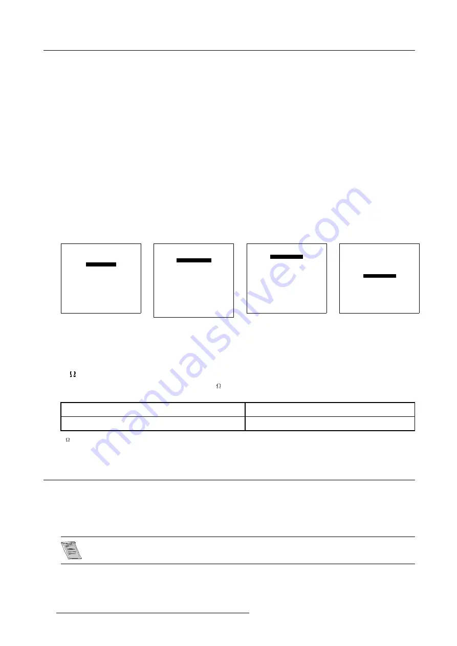
to select. (menu 6-1)
The
Choose a Setup Pattern
menu will be displayed.
3. Push the
↑
or
↓
keys to select
Selected Source
and press
ENTER
. (menu 6-2)
The
Random Access
menu will be displayed.
4. Push the
↑
or
↓
keys to select
Picture Tuning
and press
ENTER
. (menu 6-3)
The
Picture Tuning
menu will be displayed.
5. Push the
↑
or
↓
keys to highlight
Port 2: Video.
6. Press
ENTER
to toggle between
Video
or
S-Video
.
7. Press
ADJUST
to return to operational mode.
ADJUSTMENT MODE
Select a path from below :
RANDOM ACCESS
INSTALLATION
SERVICE
Select with
↑
or
↓
then <ENTER>
<EXIT> to return
Menu 6-1
Choose a setup pattern from
below:
SELECTED SOURCE
GENLOCKED PATTERN
INTERNAL # PATTERN
Select with
↑
or
↓
then <ENTER>
<EXIT> to return
Menu 6-2
RANDOM ACCESS ADJUSTMENT MODE
PICTURE TUNING
GEOMETRY
CONVERGENCE
FOCUSING
COLOR SELECT
SOFT EDGE
DRIVER VOLTAGE
Select with
↑
or
↓
then <ENTER>
<EXIT> to return
Menu 6-3
PICTURE TUNING
COLOR BALANCE
CONTRAST MODULATION
SYNC: FAST
PEAKING
CLAMP MODE: NORMAL
PORT 2:
VIDEO
LINE MULTIPLIER
Select with
↑
or
↓
then <ENTER>
<EXIT> to return
Menu 6-4
Note on loop-through
When using the Port 2 loop-through output, set the termination switch to the ’OFF’ position.
75
Termination Switch for S-Video
Terminate the S-Video input of the projector using the 75
switch next to the S-Video input, when the projector operates alone or
when the projector is the last unit in loop-through configuration.
The switch is set to ON
Signal Terminated
The switch is set to OFF
Signal Not Terminated
Table 6-5
75
Termination switch
6.4 RGB Analog Source to Port 3
Which signal to Port 3?
Connect your RGB source with sync on green, composite or separate sync via an interface to Port 3. Always use an interface (e.g.
Barco Magik Interface R9828120) when a computer and local monitor have to be connected to the projector as the signal cable
coming from the computer is limited to 60 cm due to interferences. The RGB analog input accepts only sources with a horizontal
frequency of 32 kHz and higher.
To connect a source lower than 32 kHz, an Optional D Limo Pro (R9828631) has to be installed.
38
R5976354 BARCOREALITY 908 SPLIT PACK 10092002
Содержание BarcoReality 908
Страница 1: ...SIMULATION PRODUCTS BARCOREALITY 908 SPLIT PACK R9040080 INSTALLATION MANUAL 10092002 R5976354 00...
Страница 4: ......
Страница 6: ......
Страница 8: ...Table of contents 2 R5976354 BARCOREALITY 908 SPLIT PACK 10092002...
Страница 12: ...1 Safety Instructions 6 R5976354 BARCOREALITY 908 SPLIT PACK 10092002...
Страница 18: ...2 Packaging and Dimensions 12 R5976354 BARCOREALITY 908 SPLIT PACK 10092002...
Страница 22: ...3 Installation Guidelines Image 3 4 Front Table positioning 16 R5976354 BARCOREALITY 908 SPLIT PACK 10092002...
Страница 23: ...3 Installation Guidelines Image 3 5 Front Ceiling positioning R5976354 BARCOREALITY 908 SPLIT PACK 10092002 17...
Страница 26: ...3 Installation Guidelines 20 R5976354 BARCOREALITY 908 SPLIT PACK 10092002...
Страница 36: ...4 Installation Setup 30 R5976354 BARCOREALITY 908 SPLIT PACK 10092002...
Страница 40: ...5 AC Power 34 R5976354 BARCOREALITY 908 SPLIT PACK 10092002...
Страница 52: ...6 Source Connections 46 R5976354 BARCOREALITY 908 SPLIT PACK 10092002...
Страница 68: ...A Gamma Corrections 62 R5976354 BARCOREALITY 908 SPLIT PACK 10092002...
Страница 71: ...B Material Safety Data Sheet Image B 2 R5976354 BARCOREALITY 908 SPLIT PACK 10092002 65...
Страница 72: ...B Material Safety Data Sheet 66 R5976354 BARCOREALITY 908 SPLIT PACK 10092002...


