


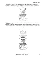


7. Hold the new optical window on the sides and carefully place it in the correct position. Exert pressure on the corners
and make sure that the window is perfectly attached to the scanner body without any tilt. Press until the gap between
the window assembly and the yellow housing is similar to the original window's gap.
8. Snug the 4 Tuflok
®
screws, but do not overtighten them. Use a 2.5 mm × 100 mm ball-end hex screwdriver with a
shaft long enough to avoid damaging the optical window.
9. Tighten the screws with a torque wrench (tightening torque of 0.5 Nm with the 2.5 mm hex key bit).
10. Remove any contamination (e.g. fingerprints, dust, etc.) on the optical window.
11. Perform a new window calibration procedure to guarantee proper working of the scanner (see
11.4.2 Calibrate a New Window
A two-meter free area around the 275° angle range of the scanner is necessary to calibrate and validate the new optical
window. Keep this area free for the entire duration of the procedure.
If the window replacement procedure was performed on a remote scanner, it must be connected to a master scanner. In this
case, the last configuration is preserved only if the optical window is replaced while the remote scanner is connected to the
same master scanner. If the remote scanner is connected to a different master scanner during window replacement, the last
configuration will be lost.
1. After replacing the window, supply power to the scanner and connect it to the configuration software.
2. Go to
Scanner
>
Discover
to list the scanners on the network.
3. From the list of scanners under
Working
, select the scanner that had its window replaced. Select the appropriate
scanner (or cluster) by double clicking on it.
4. Go to
Scanner
>
Window Replacement
and enter the password (default is admin) and click
OK
.
5. Carefully read the disclaimer. By clicking
OK
, you accept the terms and disclaimers contained herein.
6. Select the device undergoing the window replacement. If there is only one unit, select Master or Device 0. The first
remote would be Device 1, second would be Device 2, and the third would be Device 3, etc. Enter the serial number
of the new window and select
Next
.
7. If another box comes up that asks you to
Proceed
or
Change
, select
Proceed
to move to the next phase or
Change
to start over.
8. The
Window Replacement
popup window should come up stating 'Window Calibration will start now. A 2m free area
around the 275° angle range of the Laser Scanner is necessary. Proceed?' If the scanner is set up in such an area,
select
Yes
. If the scanner is not in such an area, the calibration process cannot be performed, so select
No
.
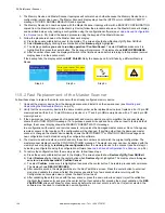
After
Yes
is selected, the window calibration process begins. The scanner first switches to an offline status (black
display), then to offline test mode, displaying the WINDOW REPLACE message. A
Window Replacement
popup
window displays in the software to state calibration is in progress.
If the window is on a REMOTE unit, the master shows the
Configuration not Accepted
icons (white background)
because the outputs will be off no matter what. The scanner will go dark at the beginning and end of the process.
9. If the test area is not compliant, an error message displays on the software. Clear the required area and retry the
calibration.
SX Safety Laser Scanner
122
www.bannerengineering.com - Tel: + 1 888 373 6767
Содержание SX5-B
Страница 135: ...Index M mute sensor 69 mute switch 69 ...