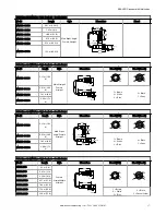
Figure 6. Option 1: Use a SI-RFA-TK Reset Connector in series with ISD Device. If available, set the power supplies for parallel output.
1
E-Stops with ISD
E-Stop without ISD
8
SI-RFA-TS
SI-RFA-TS
SI-RFA-TS
SI-RFA-TS
SI-RFA-TS
Power
#2
24Vdc 0Vdc
Bn
Bu
Power
Safety
Monitoring
Module
24Vdc 0Vdc
OSSDs
Bn
Bu
Wh
Bk
24Vdc
0Vdc
SI-RFA-TS
4-pin male connection
SI-RFA-TK
SI-RFA-P Termination
MQDEC-4xxSS or DEE2R-8xxD
MQDC-4xx
Component Key
8-pin female connection
MQDEC-4xxSS
SSA-ISD-TCA
SI-RFA-TK
MQDC-4xx
SI-RFA-P
DEE2R-8xxD
Note: Option 1 can only be used if the chain contains an SI-RFA-TS connector (the SI-RFA-TK cannot be
connected to an SSA-ISD-TCA).
Figure 7. Option 2: Replace the terminator with a power supply. The OSSD1 and OSSD2 wires at power supply #2 must be connected to +24 V DC. If
available, set the power supplies for parallel output.
1
E-Stops with ISD
E-Stop without ISD
8
SI-RFA-TS
SI-RFA-TS
SI-RFA-TS
SI-RFA-TS
SI-RFA-TS
Power
Safety
Monitoring
Module
24Vdc 0Vdc
OSSDs
Bn
Bu
Wh
Bk
24Vdc
0Vdc
SI-RFA-TS
4-pin male connection
SI-RFA-TK
SI-RFA-P Termination
MQDEC-4xxSS or DEE2R-8xxD
MQDC-4xx
Component Key
8-pin female connection
MQDEC-4xxSS
SSA-ISD-FSA
MQDC-4xx
DEE2R-8xxD
Connect OSSD1 and
OSSD2 (white and black
lines) to +24 V dc
Power
#2
24Vdc
0Vdc
Bn
Bu
SSA-ISD Connect with Indication
10
www.bannerengineering.com - Tel: + 1 888 373 6767


