Demo Kit
EZ-SCREEN
®
LP Safety Light Screen
STEP 1
Set DEMO1 program
STEP 2
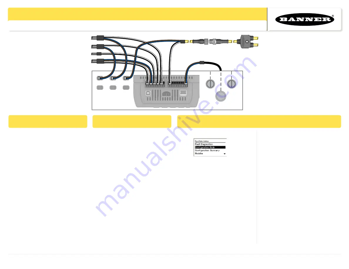
Connect EZ-SCREEN
Banner Engineering Corp. 9714 Tenth Ave. North, Minneapolis, MN USA 55441 • Phone: 763.544.3164 • www.bannerengineering.com
(using SC22-3 demo case)
STEP 3
Re-configure DEMO1
Mom-NO
24V dc
From STB Button
From STB Button
From SI-QS90
From E-Stop Button
To Receiver
To Emitter
CSB Splitter Cordset
EZ-SCREEN
Interconnect Cordset
1.
Press
ESC
to enter the System menu.
2. Select Configuration Mode, (OK). Enter
password
0000 (OK)
. Press
OK
to the
Caution message.
3. Select
Configuration File (OK)
4. Select
Edit Configuration (OK)
5. Rename configuration, e.g., TRN1A
6. Select
Inputs (OK)
,
Add Input (OK)
,
Safety Input (OK)
7. Select
Optical Sensor (OK)
8. Enter name, e.g., EZS LP
(OK)
9. Select
Circuit Type (OK)
,
Select
Dual Channel PNP (OK)
1. Hook up components and configure
the SC22-3/-3E for DEMO1 program
as described on the SC22-3 Demo
setup card (p/n 132456).
2. Verify operation of E-Stop button,
SI-QS90 Guard Interlocking switch,
and the STB Two-Hand Control to
illuminate all three SO EZ-LIGHT
indicators. This is described in “Step
4” on the SC22-3 Demo setup card.
1. Connect EZ-SCREEN LP emitter
and receiver (configured for default
settings) to the CSB Splitter cordset.
Ensure that emitter and receiver are
not looking at each other. (OSSD
must remain OFF until step 3, #16).
2. Connect CSB Splitter cordset to the
“EZ-SCREEN Interconnect Cordset”
(8-pin M12/Euro cordset found in the
SC22 demo).
3. Connect the OSSDs terminal to S12
and S13 (black and white wires).
4. Connect Power terminal to 24V dc
(brown and blue wires)
.
10. Select
Edit Terminals (OK)
, change
left terminal number to S12 and right
terminal number to S13 by using up/
down arrow keys
(OK)
.
11. Select
Map Outputs (OK)
, select
SO1
(OK)
, select
SO2 (OK)
, select
Save
(OK)
and select
Done (OK)
12. Press
OK
to continue, press
ESC
and
select
Save Configuration (OK)
13. Select
Confirm Configuration (OK)
and press
OK
until
Done
appears,
then select
Done (OK)
.
14. Select
Exit Configuration Menu (OK)
15. Press and release “System Reset” on
Demo Box.
16.
Align EZ-SCREEN and ensure the
outputs are ON (Green status LED
ON).
Activate Demo
as described in
“
Step 4
” of the SC22-3 Demo setup
card (p/n 132456).


