Banner ES-TA-3F1 Скачать руководство пользователя страница 11

E-Stop Safety Module –

Model ES-TA-3F1

5.2  Periodic Checkout Requirements 

The functioning of the Emergency Stop system (including the E-Stop Safety Module
and the guarded machine) must be verified on a regular periodic basis to ensure proper
operation (see also the machine manufacturer’s recommendations). 

Procedure:

1) With the machine running, activate one Emergency Stop switch (open its

contacts). Verify that the machine stops. (The K1 and K2 indicators should turn
OFF simultaneously. If either indicator does not go OFF, check the E-stop
indicators. The indicators for the activated Emergency Stop switch should be OFF,
as well as indicators for E-stops with higher numbers. For example, if E-stop #6 is
activated, the indicators for #6, #7, #8, #9 and #10 should all go OFF
simultaneously.) If all E-stop indicators are OK but either or both K1 and K2
indicators are ON, disconnect the input power and check all wiring. Repeat this
step after the cause of any problem has been corrected.

2) Return the Emergency Stop switch to its closed-contact position. Close and open

the Reset switch (if the controller is in Auto Reset mode, this action is not
necessary). The machine must not start at this point. Initiate the machine startup
procedure (per manufacturer’s instructions). Verify that the machine restarts in
correct sequence.

3) Repeat the above checkout procedure for each E-stop switch, individually (ES1

through ES10).

5.3 Normal Operation 

Following are examples of LED status indication and DeviceNet information for typical
E-Stop Safety Module RUN, STOP, and FAULT conditions.
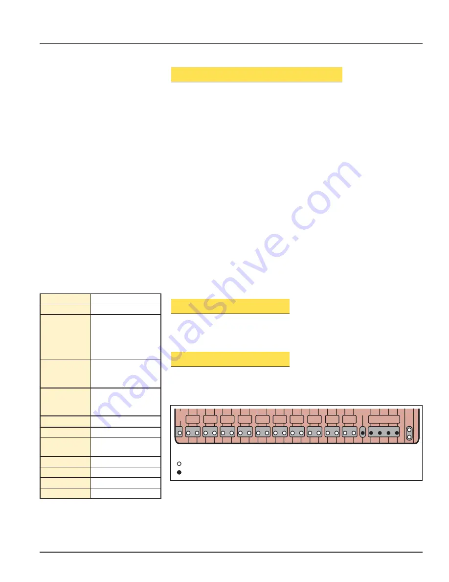
5.3.1  RUN Condition

The following LED status represents a normal run condition, where all E-stop switches
are closed, and the E-Stop Module has been reset so that K1 and K2 output contacts
are closed:

ES4

A

B

ES3

A

B

ES2

A

B

ES1

24V

DC

+

PWR

A

B

ES5

A

B

ES6

RESET

A

B

MONITOR

1

2

3

K1

K2

4

ES8

A

B

ES7

A

B

ES9

A

B

ES10

A

B

Indicator Key

Indicator "ON"

Indicator "OFF"

Figure 7. Indicator status for normal RUN condition

Operating mode:

OK (Go)

E-stop Inputs:

All Closed

Monitor Inputs:

Mon 1 Open
(NOTE: unused,
jumpered monitor
contacts will not be
listed as open)

Reset Mode:

Manual Reset
(or Auto Reset,
depending on selection)

Reset Input:

- - - - - -
(or Disabled if in Auto
Reset mode)

K1 Relay:

Energized

K2 Relay:

Energized

Autobaud:

On (or Off, depending
on selection)

Fault Type:

No Fault

Action 1:

- - - - - -

Action 2:

- - - - - -

Action 3:

- - - - - -

A normal RUN condition is reported to
DeviceNet as follows:

Buy: www.ValinOnline.com | Phone 844-385-3099 | Email: [email protected]

Содержание ES-TA-3F1

Страница 1: ...witch circuits for a contact failure or wiring fault Diverse redundant input monitoring circuit DeviceNet monitoring of status and diagnostic information Auto reset or monitored manual reset Two output switching channels for connection to control reliable power interrupt circuits Designed to comply with standards UL991 EN418 and EN954 1 Safety Category 4 For use in functional stop category 0 appli...

Страница 2: ...ety Module in any particular application are satisfied Extreme care is urged that all legal requirements have been met and that all installation and maintenance instructions contained in this manual are followed U S Standards Applicable to Use of Emergency Stop Safety Modules ANSI B11 Standards for Machine Tools Safety Requirements for the Construction Care and Use Available from Safety Director A...

Страница 3: ... for failures If the Safety Module detects failure of any contact of either the input E stop switches or the output relays the Safety Module output is disabled and cannot be reset The two switching output circuits of the Safety Module are rated for up to 250V ac at up to 4 amps resistive load The model ES TA 3F1 E Stop Safety Module also provides a selectable automatic or manual reset function Key...

Страница 4: ...ator control station and at other operating stations where emergency shutdown is required Stop and Emergency Stop push buttons must be continuously operable from all control and operating stations where located Actuators of Emergency Stop devices must be colored RED The background immediately around the device actuator must be colored YELLOW The actuator of a push button operated device must be of...

Страница 5: ...ble enclosure using the supplied hardware Leave a minimum 1 cm 1 4 gap between the Safety Module housing and adjacent housings to allow room for potential board replacement at a later date The ES TA 3F1 E Stop Safety Module should be configured before initial checkout and use see section 4 4 and 4 5 35 0 mm 1 38 DIN Mounting Slot Slot for Screws 2 M3 5 x 0 6 mm 2 DIN Mounting Tab Supplied 60 8 mm ...

Страница 6: ...rcuit Reset switch can be any mechanical switch such as a normally open momentary switch or a two position key switch The Reset switch must meet the requirements listed in the Product Specifications on page 20 The Reset switch connects between terminals 22 and 50 of the Safety Module The Reset switch must be located outside and not accessible from the area of dangerous motion and must be positione...

Страница 7: ...led as shown across the load of the Master Stop Control elements MSC1 MSC2 MSC3 and MSC4 NEVER install suppressors directly across the output contacts of the E Stop Safety Module It is possible for suppressors to fail as a short circuit If installed directly across the output contacts of the Safety Module a short circuited suppressor will create an unsafe condition which could result in serious in...

Страница 8: ...ove 63 and the current address of the E Stop Safety Module as recognized by the DeviceNet controller was set with the MAC ID address rotary switches above 63 4 4 Selecting Auto or Manual Reset Mode The E Stop Safety Module is switchable between Auto and Manual reset the factory setting is Manual When Manual reset is selected the E Stop Safety Module may be reset only by a manual Reset switch When ...

Страница 9: ...ndicators are ON If Auto Manual Reset selector is set to Auto mode verify that K1 K2 and all E stop indicators are ON Reset and all monitor indicators are OFF 4 Close the Reset input if Auto Manual Reset selector is set to AUTO mode go to step 5 Verify that the Reset and K1 LED indicators go ON K2 indicator should remain OFF Open the Reset switch and verify that the Reset indicator is OFF The K1 a...

Страница 10: ...ety Module should be mounted inside a lockable enclosure For security reasons the key to the lockable enclosure must be in the possession of a Qualified Person or Persons A Qualified Person is a person who by possession of a recognized degree or certificate of professional training or who by extensive knowledge training and experience has successfully demonstrated the ability to solve problems rel...

Страница 11: ... The machine must not start at this point Initiate the machine startup procedure per manufacturer s instructions Verify that the machine restarts in correct sequence 3 Repeat the above checkout procedure for each E stop switch individually ES1 through ES10 5 3 Normal Operation Following are examples of LED status indication and DeviceNet information for typical E Stop Safety Module RUN STOP and FA...

Страница 12: ...r Off depending on selection Fault Type E Stop 4 Fault Action 1 Check E Stop 4 Action 2 New Relay Board Action 3 New Comm Board ES4 A B ES3 A B ES2 A B ES1 24V DC PWR A B ES5 A B ES6 RESET A B MONITOR 1 2 3 K1 K2 4 ES8 A B ES7 A B ES9 A B ES10 A B Indicator Key Indicator ON Indicator OFF Figure 9 Typical indicator status for FAULT condition contact B of E stop switch ES4 remains closed upon actuat...

Страница 13: ...if switch 4 has been activated the indicators for switches 4 5 6 7 8 9 and 10 will be OFF To reset begin by verifying that the problem prompting the E stop procedure has been corrected The E stop switch indicator and all those to the right of it on the control module front panel should go ON Then activate the Reset switch connected to the E Stop Safety Module and reset the E stop switch indicated ...

Страница 14: ... network is properly terminated and grounded per DeviceNet specifications 4 Check for insufficient network power supply Red Flashing Connection timeout or no power to E Stop Safety Module 1 Check input power to the E Stop Safety Module 2 Check DeviceNet I O connection time out expected packet rate EPR parameter setting and or problem with DeviceNet master OFF No network power or off line 1 Check t...

Страница 15: ...ex fingers opposite each other at the center of the cover Place your index first finger on the edge of the cover Pull upward on the cover center while your index finger holds the cover edge down Pull until the cover edge clears the slots in the housing 3 Gently push the sides of the module housing outward at the top corners to dislodge the four locking tabs on the two circuit boards from the slots...

Страница 16: ...er of the cover into place until it is flat 4 Remount the Module and replace the wiring barriers by pushing them down into their receptacles Take care to match the terminal labels on the wiring barriers with the terminal labels on the board headers If it ever becomes necessary to return an E Stop Safety Module to the factory please do the following 1 Contact the Banner Factory Application Engineer...

Страница 17: ...ceNet Specifications Bus Status Indicator A bi colored red green LED visible on the control module indicates network status Green Steady On line connected allocated to master Flashing On line not connected allocated to master if Autobaud is ON address and baud rate ok Red Steady Critical network fault or duplicate node address detected Flashing Connection timeout or no power to light screen Green ...

Страница 18: ...tion size of 0 bytes Assembly instance 2 is used as the response data for the COS command A COS command is issued in response to a change in the E Stop Module operating mode Produced connection size of 1 byte Consumed connection size of 0 bytes Byte Bit 7 Bit 6 Bit 5 Bit 4 Bit 3 Bit 2 Bit 1 Bit 0 0 E Stop Inputs Operating Mode 1 Reset Mode Invalid Reset Mode Reset Input Invalid Reset Input K1 Rela...

Страница 19: ...he reset mode is unknown Reset Mode 0 The reset mode is manual 1 The reset mode is automatic Reset Input Invalid 0 The status of the reset input is known 1 The status of the reset input is unknown disabled Reset Input 0 The reset input is open 1 The reset input is closed K1 Relay Invalid 0 The state of the K1 relay is known 1 The state of the K1 relay is unknown K1 Relay State 0 The K1 relay is OF...

Страница 20: ...ch must have two normally closed contacts each capable of switching 20 to 150mA 12 to 18V dc Reset switch must have one normally open contact capable of switching 20 to 150mA 12 to 18V dc Master Stop Control MSC Element monitor contacts must be capable of switching 20 to 250 mA 12 to 18V dc Enclosure Size See Figure 2 page 5 Material polycarbonate Rated NEMA 1 IEC IP20 Mounting Mounts to standard ...

Отзывы: