


4.1.2 Factory Settings
Of the 15 available control module ID values (A through O), the factory software setting is A. Selectable communication
baud rates are 9600, 19200, and 38400; the factory setting is 9600. See
Selected Controller and Serial Communication
(p.
18) for information on changing these settings.
4.2 System Alignment
The emitter/receiver pairs have a wide field of view and are easy to align. The recommended distance between the emitter
and receiver ranges from 380 mm to 1829 mm (15 in to 72 in). Shorter sensor separation can be achieved; consult Banner
Engineering for details.
Perform the Alignment process at System installation and repeat it every time one or both of the sensors is moved.
Alignment of the System can be specified automatically using either the Alignment routine of the configuration software or
the Alignment switch on the control module’s front panel.
The System also may be aligned remotely, using pins 14 and 15 on the terminal block. Apply 10 V dc to 30 V dc power to
the pins to approximate the push-button procedure. For example, apply input signal for 3 seconds to access Alignment
mode.
1. Make sure the sensors have been wired as shown in
(p. 9).
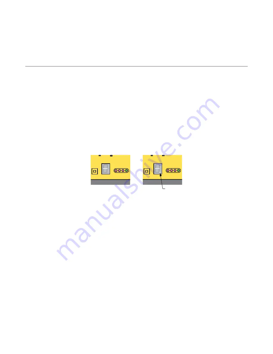
2. Apply power to the control module via terminals #1 and #2 (16 V dc to 30 V dc).
The Diagnostics Indicator shows the sensors going though a power-up test: first the receiver, then the emitter. After
the sensors have been tested and the System is ready for service, the Diagnostics Indicator shows — or —.; see
figure.
ALIGNMENT
SWITCH
R
DIAGNOSTICS
INDICATOR
OUTPUT
ALARM
GA
TE
ALIGN
150mA MAX
EMTR
RCVR
ALIGNMENT
SWITCH
R
DIAGNOSTICS
INDICATOR
OUTPUT
ALARM
GA
TE
ALIGN
150mA MAX
EMTR
RCVR
With Blanking OFF
With Blanking ON
Denotes
Blanking
Figure 14. Diagnostics Indicator Showing a Clear Condition
4.2.1 Push-Button Alignment Routine
Re-align the System at installation or whenever the emitter and/or receiver is moved.
1. Press the Alignment switch on the control module front panel for 3 seconds.
The letter A displays on the Diagnostics Indicator; the System is learning a clear condition.
2. Rotate the sensors as required (but do not change the distance between them).
When the green Alignment LED is displayed on the control module and receiver, the sensors are adequately aligned.
3. To leave Alignment mode, press the Alignment switch for 3 seconds.
During the alignment procedure, the System polls each receiver channel to measure excess gain and performs a coarse
gain adjustment. When the System exits the alignment procedure, each channel’s signal strength is stored in non-volatile
memory. The System is now ready for operation and does not require re-alignment unless the emitter or receiver is moved.
4.2.2 Software Alignment Routine
The green LED indicator on the receiver and also on the control module continuously displays Alignment status. When all
unblanked beams are clear, the green Alignment indicators are ON. To better understand blocked, clear, and blanked
beams, launch the Alignment routine (press F8 or select Alignment under the MINI-ARRAY menu). The screen shows the
state of all of the beam channels, grouped into sets of 16.
Key information provided on the Alignment screen is the sensor size, plus the number of beams blocked, made, and
blanked. The sensor size is given the title of Total; this refers to the total number of beam channels in the array. The number
of beams blocked is a running total of blocked beams, excluding any blanked beams. The Made value is a count of
unblocked beams. The Blanked value is a count of the number of beam channels that are blanked (channels that are
ignored for measurement mode applications).
A-GAGE
®
High-Resolution MINI-ARRAY
®
14
www.bannerengineering.com - Tel: + 1 888 373 6767