


Serial Transmission
Specifies the type of data transmitted
from the control module to its host
after each scan.
Measurement Mode
Result: Data
transmitted will reflect the Analysis
Mode selections.
All Mode: Transmits all data.
Max. Meas. Mode: Sends only the largest
measurement in each measuring event,
to decrease transmission size and speed
response. Choose to send when the
array is clear or send at the host’s
request.
Transmission Type: ASCII or Binary,
defines the format in which the data
will be sent.
Serial Options: Suppress Clear Data
or Suppress Header to decrease
transmission size and speed response.
Analysis (Measurement)
Mode Selection
Choose the measurement
option that best tells you
the size and/or position
of objects as they
relate to the array.
Control Mode Selection
Continuous Mode: The control
module constantly polls
the array for status.
Host Mode: The control module
polls the array for status when
prompted by a host controller.
Gate Mode: The control module
polls the array for status when
prompted by an input from a
Gate sensor.
Scanning Method
Straight scan polls each beam
sequentially to determine the
target object’s overall size. This is
the most accurate and precise
measurement, but also the most
time-consuming.
Single Edge scan requires the
target object to block beam 1
(closest to the sensors’ cabled
ends), then conducts a time-saving
binary search to “hunt” for the
target’s overall height (one
variable edge).
Double Edge scan conducts a
time-saving search of the entire
array to “hunt” for the target’s
Set Point and
Hysteresis Selection
Assigns the set point to
determine where within
the array the output(s)
will respond and
hysteresis values to
smooth output response.
Trigger/Trigger Channel Number
May be used to trigger (or gate) the scan sequence of another
A-GAGE High-Resolution MINI-ARRAY controller; in straight
scanning mode, it defines when during each scan discrete Output
#2 will change state.
Scan #:
(1-9) Analog outputs are
updated with an average value of the
data received during the selected
number of scans; discrete outputs
respond only if the received data is
identical for all of the selected number
of consecutive scans.
Analog and Discrete
Output Assignment
Assigns an analysis
(measurement) mode
to each output.
Alarm: Causes the control module to
turn on discrete Output #2 whenever
the System detects a sensing error or
if the optical signal becomes marginal.
Selected Controller
Identifies the specific
control module being
configured.
Serial Communication
Changes the
identification
and baud rate of the
controller being configured.
Zero Value
Zero Value is used to specify the
analog output when the
measurement mode value is
zero. The user can specify a
value of LAST, NULL, or SPAN.
LAST:
Output holds the last non-zero value before the
light screen became clear.
NULL: Provides the minimum value.
SPAN:
Provides the maximum value.
overall width (two variable edges)
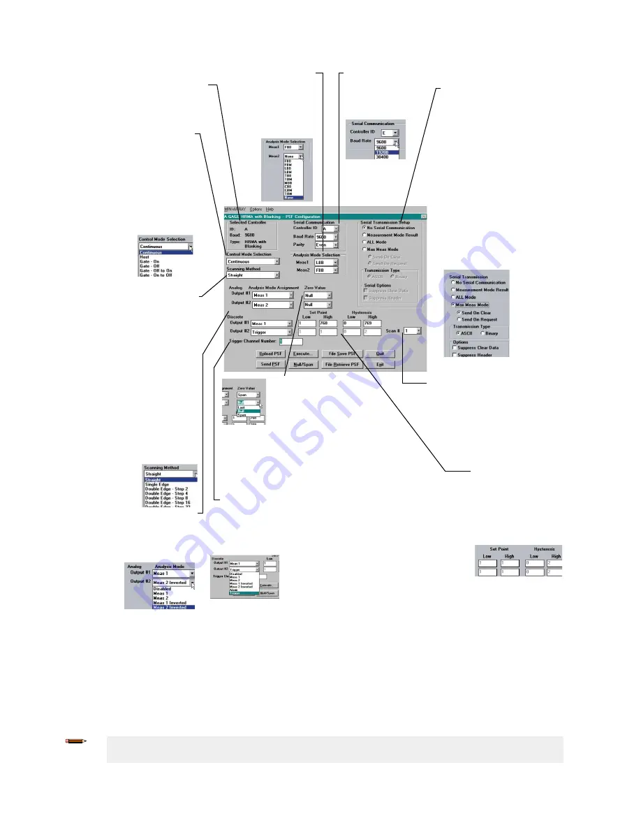
Figure 19. Use the PSF Configuration Screen to Program Each Control Module Individually
4.3.1 Selected Controller and Serial Communication
The Selected Controller box displays information about the control module being configured. Two of these settings may be
changed in the Serial Communication box. The settings selected and displayed in these boxes are those used to identify
the control module during the Ping routine.
Controller ID (assigned a letter, A through O) is used to identify each individual control module when multiple discrete-
output control modules (up to 15) are connected on one EIA-485 party line.
Note: Analog output control modules do not offer RS-485 communication; choose any ID letter (A
through O) when programming an analog-output control module.
A-GAGE
®
High-Resolution MINI-ARRAY
®
18
www.bannerengineering.com - Tel: + 1 888 373 6767