Technical data • Individual components
88
Panel PC 2100 swing arm user's manual V1.12
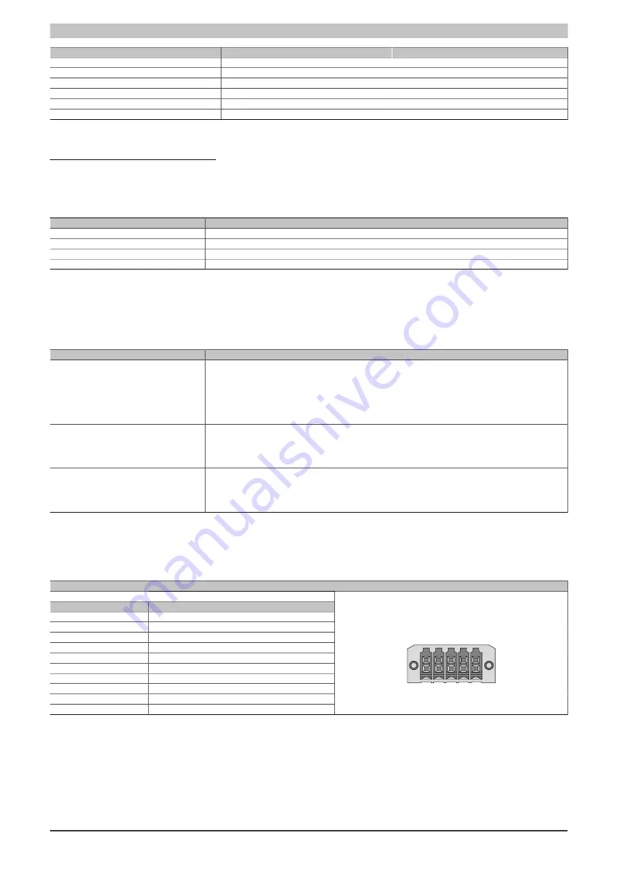
Bit timing register 1
Bit timing register 0
Baud rate
00h
14h
1000 kbit/s
80h or 00h
1Ch
500 kbit/s
81h or 01h
1Ch
250 kbit/s
83h or 03h
1Ch
125 kbit/s
84h or 04h
1Ch
100 kbit/s
89h or 09h
1Ch
50 kbit/s
Table 71: CAN driver settings
CAN2 - Bus length and cable type
The type of cable to be used depends largely on the required bus length and number of nodes. The bus length is
determined by the bit rate. In accordance with CiA (CAN in Automation), the maximum bus length is 1000 meters.
The following bus lengths are permitted with a maximum oscillator tolerance of 0.121%:
Extension
Transfer rate
≤1000 m
Typ. 50 kbit/s
≤200 m
Typ. 250 kbit/s
≤100 m
Typ. 500 kbit/s
<20 m
1)
Typ. 1 Mbit/s
Table 72: CAN2 - Bus length and transfer rate
1)
The specified cable length is only valid with the values specified in
. Cable lengths additionally depend on the values in the
timing register.
The material used for the cable should have all or most of the following properties in order to achieve an optimal
transfer rate.
CAN cable
Property
Signal lines
Cable cross section
Wire insulation
Conductor resistance
Stranding
Shield
2x 0.25 mm² (24 AWG / 19), tinned copper stranded wire
PE
≤82 Ω/ km
Wires stranded in pairs
Paired shield with aluminum foil
Grounding line
Cable cross section
Wire insulation
Conductor resistance
1x 0.34 mm² (22 AWG / 19), tinned copper stranded wire
PE
≤59 Ω/km
Outer sheathing
Material
Features
Complete shielding
PUR mixture
Halogen-free
From tinned copper wires
Table 73: CAN cable requirements
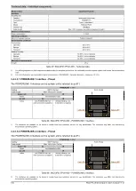
3.4.1.3.4 X2X Link master interface - Pinout
The X2X Link master interface on the system unit is referred to as IFx.
X2X Link master - IFx
1)2)
The electrically isolated X2X Link master interface is a 10-pin connector.
Pin
Assignment
1
X2X H
2
Shield
3
X2X L
4
X2X GND
5
-
6
-
7
-
8
-
9
-
10
-
10-pin, male
1 3 5 7
2 4 6 8 10
9
Table 74: 5ACCIF01.FPCC-000 - X2X Link master interface
1)
The interfaces, etc. available on the device or module have been numbered as such for easy identification. This numbering may differ from that used by
the particular operating system.
2)
This interface can only be used in Automation Runtime and is referred to as IF2 in Automation Studio / Automation Runtime. It is not a "PC interface" and
therefore not shown in BIOS.
3.4.1.3.5 Shielding
For the interfaces on the 10-pin female connector, the interface shield can be put on pin 2 of the female connector.


