
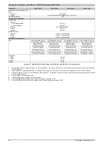

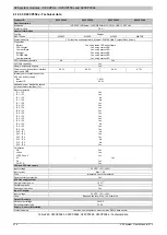
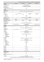
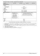
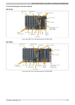


X20 system modules • X20 CPUs • X20CP158x and X20CP358x
X20 system User's Manual 3.10
929
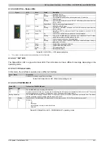
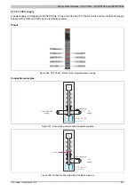
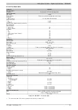
4.12.3.15 POWERLINK interface (IF3)
POWERLINK V1
Switch position
Description
0x00
Operation as managing node.
0x01 - 0xFD
Node number of the POWERLINK node. Operation as controlled node.
0xFE - 0xFF
Reserved, switch position not permitted
Table 290: POWERLINK V1 - Node numbers
POWERLINK V2
Switch position
Description
0x00
Reserved, switch position not permitted
0x01 - 0xEF
Node number of the POWERLINK node. Operation as a controlled node.
0xF0
Operation as a managing node.
0xF1 - 0xFF
Reserved, switch position not permitted
Table 291: POWERLINK node number
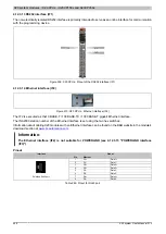
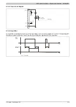
Ethernet mode
In this mode, the interface is operated as an Ethernet interface. The INA2000 station number can be set using the
B&R Automation Studio software.
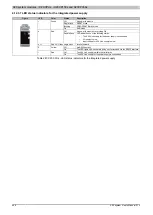
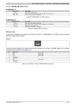
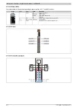
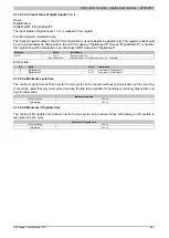
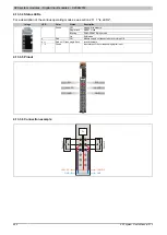
Pinout
Information about cabling X20 modules with an Ethernet interface can be found on the B&R website in the module's
download section at
Pin
Assignment
1
RxD
Receive data
2
RxD\
Receive data\
3
TxD
Transmit data
4
Termination
5
Termination
6
TxD\
Transmit data\
7
Termination
8
Termination
Table 292: X20 CPUs - Pinout for POWERLINK interface (IF3)


