X20 system modules • Counter modules • X20DC1976
770
X20 system User's Manual 3.10
4.11.12.8.3 Encoder - Configuration
The following registers are used for setting functions and configuring the module.
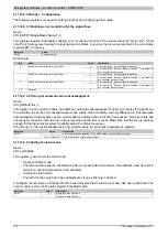
4.11.12.8.3.1 Enabling error monitoring for the signal lines
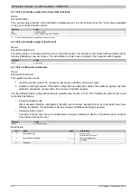
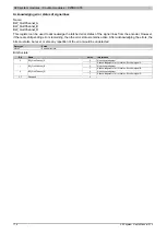
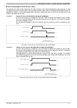
Name:
CfO_BWCNTEnableMaskChannel7_0
This register requires individually enabling error monitoring for each of the signal channels. "Open line", "short
circuit" and "voltage level too low" are reported as error states. Any errors that occur are reported in the error status
Data type
Value
USINT
See bit structure.
Bit structure:
Bit
Name
Value
Information
0
Error monitoring - Encoder Signal A disabled
0
Enable error monitoring for signal A lines
1
Error monitoring - Encoder Signal A enabled - Only default in
bus controller function model
0
Error monitoring - Encoder Signal B disabled
1
Enable error monitoring for signal B lines
1
Error monitoring - Encoder Signal B enabled - Only default in
bus controller function model
0
Error monitoring - Encoder Signal R disabled
2
Enable error monitoring for signal R lines
1
Error monitoring - Encoder Signal R enabled - Only default in
bus controller function model
3 - 7
Reserved
0
4.11.12.8.3.2 Timing for automatic error acknowledgment
Name:
CfO_BWQuitTime_0
This register can be used to enable an additional automatic acknowledgment of the error status through timing.
If a valid time is set, then the acknowledgment can still be made manually, the only difference is that automatic
acknowledgment will take place on the module after the defined amount of time has passed. If the error state has
not yet been corrected, then the error status remains and the time is reset. Make sure that the time is set long
enough for the higher-level system to reliably detect the status messages.
If the timing = 0, then acknowledgment is only possible using the cyclic acknowledgment registers.
Data type
Value
Information
0
No automatic acknowledgment - Only default in bus controller function model
UDINT
1 to 2.147.483.647
Time for automatic acknowledgment [μs]
4.11.12.8.3.3 Setting the latch mode
Name:
CfO_LatchMode
This register is used to set the latch mode:
•
Single shot latch mode:
The latch function must be enabled/set. After a successful latch procedure, the activation must be reset in
order for a new latch procedure to be activated.
•
Continuous latch mode:
The latch function only has to be enabled/set as long as latching is desired.
A changed counter state on Encoder01LatchCount indicates that the latch procedure has been performed. The
counter value is stored in the latch register Encoder01Latch.
Data type
Value
Information
0
Single shot latch procedure
USINT
1
Continuous latch procedure

