


X20 system modules • Digital output modules • X20DO8232
X20 system User's Manual 3.10
1237
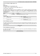
4.15.22.7 Output circuit diagram
1
Logic
High-side
12 V monitoring
12 V
External Supply
GND
Output x
12 V
GND
External
Power supply
Reverse polarity
protection
External Supply
12 V GND
1 GND
12 V
External Supply
1
I/O status
LED (orange)
Output monitoring
Output status
Figure 374: Output circuit diagram
4.15.22.8 Switching inductive loads
Environmental temperature: 35°C, 4 outputs (1,3,5,7 or 2,4,6,8) with the same load.
0.1
1
10
100
Coil resistance
[Ω]
Coil inductance
10 mH
100 mH
1 H
10 H
100 H
100
500
10
5
Max. switching cycles / second
(with 90% duty cycle)
14.4 V
12.0 V
Switching voltage:
Figure 375: Switching inductive loads


