B&K ST140M Скачать руководство пользователя страница 11

Page 9

12999 rev 0005

System installation


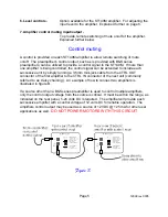
There will most likely be a number of cables involved in the installation of your home
entertainment system.  Pre-planning is essential in order to maximize system efficiency. 
We recommend the following as a means of helping you reach that goal:

Make a diagram of your proposed system by laying out the relative location of
each component in the system.  Then lay out the proposed cable runs between
them.  Number each cable and record its length on the diagram for future
reference.

Cable runs are critical in that they must be kept away from sources of power
radiation (amplifiers, power cords, heaters, etc...).  For the sake of safety, they
should also be kept out of traffic areas.

The process of optimizing the system will include the type of cable, the length of
the run, and the obstructions it must deal with along its run.  Your dealer can
advise you on the products available and their relative merits.  If building custom
length audio cables is not your strength, your dealer should be able to help you
with that as well.

When possible, use a separate AC power line for the amplifier, one that is not
shared by any other component in the system of any other house hold
component.

Tip: Take a piece of stout string (longer than the longest cable run) and mark it at each foot of length. 
Then do a mock cable run using the string, dressing it neatly along the way.  Count the divisions to the
next full foot, and add one foot to allow for some movement of the components.  This will provide you with
the ideal cable length. 

Making the connection

Before doing anything, ensure that the power switch on the amplifier’s front panel
is in the ‘off’ position.  Again, it is recommended that you locate a separate AC
power outlet for the amplifier, one that is 

not

 shared by any other audio

component in the system or any other house hold component.  This will eliminate
the possibility of the amplifier ‘modulating’ the power being supplied to the
component and compromising the signal originating from that component.

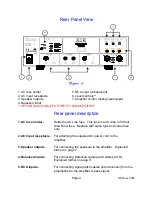
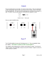
Locate the AC power cord provided with the amplifier and plug it into the power
input receptacle in the rear panel.  

Do not connect it to the AC power source

yet!

Connect the audio cables from your preamplifier’s output to the  corresponding
input connector on the amplifier.

Содержание ST140M

Страница 1: ...ST140M Single Channel Amplifier OWNER S MANUAL B K Components Ltd 12999 rev 0005...

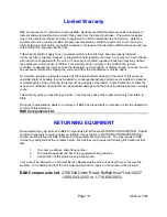
Страница 2: ...12999 rev 0005 B K Components Ltd 2100 Old Union Road Buffalo New York 14227...

Страница 3: ...es Page 3 Rear panel view Page 4 Rear panel description Page 4 5 Control muting Page 5 6 Level controls Page 6 Outputs Page 7 Inputs Page 8 System installation Page 9 Making the connection Page 9 10 T...

Страница 4: ...ct Damage can occur to your speakers if the power rating of each individual driver is exceeded by the amplifier Ensure that all the drivers in your speaker system are capable of handling not only the...

Страница 5: ...e most demanding audio signals at rated power levels Features Toroidal Transformers Efficient high current transformer for improved dynamics Discrete Circuitry More accurate and three dimensional repr...

Страница 6: ...AC Line fuse This fuse is an 8 Amp 250 Volt Slow Blow fuse Replace with same type and value fuse only 2 AC Input receptacle For attaching the supplied AC power cord to the amplifier 3 Speaker outputs...

Страница 7: ...al can be extended to include each successive unit by simply running a 3 5mm mini jack cable from the CTRL OUT connector of the first amplifier to the CTRL IN connector of the next unit commonly refer...

Страница 8: ...nal No Signal OUT Mute No Signal No Signal IN Sound Signal Note The control voltage is for muting control only Each amplifier must be connected to its own source of AC power in order for it to operate...

Страница 9: ...rs jack The black post should always be connected to the speakers jack Spade connector Banana jack Here is a typical amplifier setup The ST140M amplifier has two sets of binding posts on it They are p...

Страница 10: ...f the amplifier is in the off out position If the amplifier does not have balanced inputs then it is always in unbalanced mode Balanced XLR type connectors accept line input from the preamplifier s ba...

Страница 11: ...well When possible use a separate AC power line for the amplifier one that is not shared by any other component in the system of any other house hold component Tip Take a piece of stout string longer...

Страница 12: ...turn the amplifier off and wait 30 seconds for the amplifier to discharge Both the preamplifier and amplifier should be off Connect a playback unit CD VLD Tuner etc to the preamplifier Turn the volume...

Страница 13: ...n bass weak 1 Speakers connected out of phase 1 Check connections making sure that cables are connected to and to Loud hum or buzz on one or more channels 1 Poor ground connection in interconnect cabl...

Страница 14: ...dance 33 2 k ohms Damping factor 180 Current peak to peak 60 Amps Slew rate 14 V sec Dynamic headroom 1 5 dB S N A weighted 95 dB Voltage gain 28 Line voltage 120 220 240 VAC switchable Dimensions O A...

Страница 15: ...rms of this warranty and B K shall not be liable for any incidental or consequential damage arising out of a defect in material or workmanship of the unit during the terms of this warranty or thereaft...

Страница 16: ...12999 rev 0005 B K Components Ltd 2100 Old Union Road Buffalo New York 14227 716 656 0023 www bkcomp com...

Отзывы: