background image

8 | 

System overview | 

H5000 Operation Manual

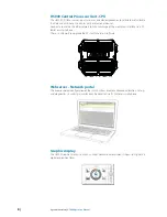
H5000 Central Processor Unit - CPU

The H5000 CPU takes sensor inputs and uses a dedicated processor to calculate and calibrate 
the data and distribute it to display units and external devices.

Connect a router via the ethernet port to take advantage of the webserver interface via a PC, 
tablet or smart-phone.

There is a USB port to upgrade the CPU with the latest software.

Webserver - Network portal

The browser-based confi guration of the H5000 system enables advanced calibration, set-up 
and diagnostics. Its web-style interface can be accessed via PC, tablet or smartphone.

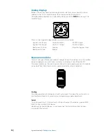
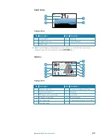
Graphic display

The H5000 Graphic Display is a 5-inch, sunlight viewable, color display. It shows sailing data in 
digital or graphical form.

Содержание H5000 Pilot

Страница 1: ...ENGLISH H5000 Operation Manual www bandg com ...

Страница 2: ...s been translated from another language Translation In the event of any conflict between any Translation of the Documentation the English language version of the Documentation will be the official version of the Documentation This manual represents the product as at the time of printing Navico Holding AS and its subsidiaries branches and affiliates reserve the right to make changes to specifications wit...

Страница 3: ...m system requirement 16 Basic System No H5000 CPU 17 Operation 17 Graphic display 18 Default graphic display pages 25 Data page transition 25 Available data pages 26 Replacing a data page 27 Menus 28 Race timer 30 Man Over Board 31 HV display support 32 Alarms 34 Damping 35 Trip log 35 Log 36 Race display 41 Diagnostics 44 H5000 Pilot Controller 45 Autopilot operation 46 Autopilot modes 49 Sensor ...

Страница 4: ...tion 67 Rudder drive 69 Commissioning 73 Response 73 Sailing 75 Steering 77 Setup 79 Webserver 82 Webserver menus 83 CPU software upgrade 84 Webserver help files 85 Operating variables 113 Example data tables 113 Polar table 114 Boat speed Heel correction 114 True wind angle correction 114 True Wind Speed correction 114 Downwind correction angle for TWS 115 Maintenance 115 Basic maintenance procedu...

Страница 5: ...e of navigation nautical terminology and practices The manual does not cover basic background information about how equipment such as radars echo sounders and AIS work Important text that requires special attention from the reader is emphasized as follows Note Used to draw the reader s attention to a comment or some important information Warning Used when it is necessary to warn personnel that the...

Страница 6: ...6 Introduction H5000 Operation Manual ...

Страница 7: ...sors for straightforward upgrades The high resolution H5000 Graphic Display is highly intuitive and delivers information on a 5 inch bonded screen with fast smooth display updates The H5000 Race Display provides segmented text numbers and target indicator for the race information you need in a glance The H5000 Autopilot brings the functionality and dedicated sailing algorithms of its record breaki...

Страница 8: ...to take advantage of the webserver interface via a PC tablet or smart phone There is a USB port to upgrade the CPU with the latest software Webserver Network portal The browser based configuration of the H5000 system enables advanced calibration set up and diagnostics Its web style interface can be accessed via PC tablet or smartphone Graphic display The H5000 Graphic Display is a 5 inch sunlight v...

Страница 9: ...to be positioned where it is needed rather than where it fits Its compact dimensions allow the 10 10 to be installed almost anywhere typical installation areas are the base of winch pedestals alongside hydraulic control panels steering pedestals or as a companionway display on the smaller yacht 20 20 HV The latest generation of the classic 20 20 mast display The 20 20 is the de facto standard for m...

Страница 10: ...rent Wind Expansion modules There are two types of Expansion module Analog and Serial The modules act as the interface between analog sensors serial devices and other in and outputs to and from the CPU The correct module must be used in conjunction with its corresponding sensors All modules are powered from the network and can supply power to the sensors connected Analog The analog module has 6 an...

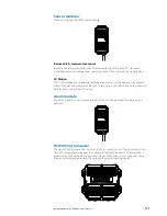
Страница 11: ...as well as pitch roll and yaw rates of the yacht allowing the CPU software to correct the wind data for errors induced by this motion Alarm module The alarm module is a network audible alarm that can be positioned anywhere on the network H5000 Pilot Computer The H5000 Pilot Computer links with the H5000 instrument system The instrument system transmits sensor information over the network to the Pi...

Страница 12: ...000 Operation Manual H5000 Pilot Controller The H5000 Pilot Controller manages all autopilot functions as well as setup and commissioning Use the H5000 Pilot Controller to select autopilot modes or manually steer the vessel ...

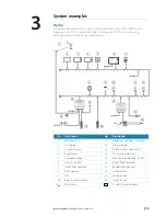
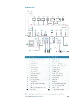
Страница 13: ...11 1 18 17 T T 13 19 16 15 14 12V PILOT 20 WIFI 1 No Description No Description 1 Masthead unit 11 Motion sensor Heel Trim only 2 HV Display 12 Alarm module 3 Graphic display 13 Wireless access point WiFi 1 4 Race display 14 Central processor unit 5 Analogue display 15 Man Overboard Button MOB 6 Zeus series MFD 16 H5000 Pilot Computer 7 H5000 Pilot Controller 17 Rudder reference unit 8 RC42 compas...

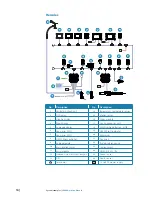
Страница 14: ... sensor 3 Graphic display 16 Alarm module 4 Race display 17 Central processor unit 5 Analogue display 18 Man Overboard Button MOB 6 Zeus series MFD 19 H5000 Pilot Computer 7 Zeus series MFD 20 Webserver 8 H5000 Pilot Controller 21 Deckman 9 Analog module 22 Rudder reference unit 10 Mast rotation sensor 23 Hydraulic ram 11 Serial module 24 NMEA 0183 Tx Rx 12 Halcyon Gyro Stabilized Compass 25 Speed...

Страница 15: ... Analogue display 20 Analog module 6 Zeus series MFD 21 Analog module 7 Zeus series MFD 22 Analog device 8 H5000 Pilot Controller 23 H5000 Pilot Computer 9 Analog module 24 Rudder reference unit 10 Analog module 25 Hydraulic ram 11 Mast rotation sensor 26 Webserver 12 Serial module 27 Deckman 13 Halcyon Gyro Stabilized Compass 28 Port Starboard speed sensor 14 GPS 29 NMEA 0183 Depth sensor 15 Baro...

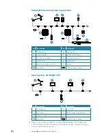
Страница 16: ...Ram 5 H5000 Central Processor Unit 10 Compass T Terminator 12V 12 Volt DC power supply Basic System No H5000 CPU 1 T T 2 3 4 12V 5 No Description No Description 1 Masthead unit 4 ZG100 GPS 2 HV Display 5 DST800 Speed Depth sensor 3 Graphic Display T Terminator 12V 12 Volt DC power supply Note A system without an H5000 CPU will only provide data from the available sensors on the network and limited...

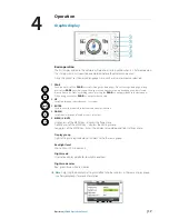
Страница 17: ... to the data pages When using a menu the PAGE key navigates back a step 2 UP Scrolls up through selected menus set values 3 ENTER Used to enter the selected sub menus and confirm selection 4 DOWN Scrolls down through selected menus set values 5 MENU LIGHTS Single press of the MENU key displays the Page menu Double press of the MENU key displays the Settings menu Long press of the MENU key Enters th...

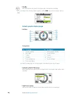
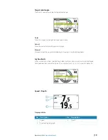
Страница 18: ...ion 1 Course Heading 7 Port Starboard indicator 2 Boat speed 8 True Wind Angle 3 Tide set 9 Laylines 4 Waypoint 10 Tide rate 5 True wind direction 11 True Wind Speed 6 True wind indicator Note See configuring the Sail Steer page for more information on using this page Configuring the Sail Steer page When navigating to a waypoint you can configure the Sail Steer page to show laylines to aid navigatio...

Страница 19: ...value of target wind angle Manual Manually input the upwind and downwind numbers into the dialog boxes Layline limits When selected will show a dotted line indicating the minimum and maximum tack gybe time period either side of the layline This can be set to 5 10 15 30 minute increments Speed Depth 1 3 2 Displayed data No Description No Description 1 Speed 3 Depth 2 Acceleration bargraph ...

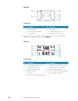
Страница 20: ... or a 60 minute history Toggle between the time periods using the UP DOWN keys Start line 3 4 1 7 8 6 11 9 10 2 5 Displayed data No Description No Description 1 Distance to port end of start line 7 Distance to starboard end of start line 2 Tide direction indicator 8 Starboard end start line indicator 3 Port end start line indicator 9 Wind indicator wind barb 4 Start line bias angle 10 Start line A...

Страница 21: ...pdated to negate the difference between the GPS position and the bow of the vessel 1 Approach the port end of the start line 2 Select ping from the start Line menu 3 Highlight Port end 4 When the bow touches the start line press the ENTER key 5 The port end mark on the start line screen will go to solid red indicating it has been pinged 6 Repeat steps 1 to 4 at the starboard end selecting ping star...

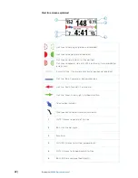
Страница 22: ...alid Invalid start line One or more ends invalid position not recorded Start line Blue Square line No bias advantage Start line Red Arrow left Port end bias Start line Green Arrow right Starboard end bias Tide direction indicator Wind speed and direction indicator wind barb 1 DIST P Distance to port end of start line 2 BIAS Start line bias angle 3 Race timer 4 DIST LINE Distance to start line perp...

Страница 23: ...be set to show 5 10 30 or a 60 minute history Toggle between the time periods using the UP DOWN keys Highway 1 2 4 6 7 8 9 10 11 5 3 Displayed data No Description No Description 1 Waypoint bearing 7 Estimated waypoint arrival time 2 Course over ground 8 Waypoint 3 Off course limit user setting 9 Course line 4 Distance to waypoint 10 Vessel indicator 5 Cross track error 11 XTE correction direction L...

Страница 24: ...7 True Wind Angle 3 Heading 8 True Wind Speed 4 Depth 9 True wind direction 5 Tide rate 10 Tide direction Autopilot 4 5 9 10 3 8 7 2 6 1 Displayed data No Description No Description 1 Set heading Wind angle 6 Heading indicator 2 Compass scale 7 Heading 3 Performance level 8 Set heading Wind Rudder angle 4 Autopilot mode indicator 9 Wind angle 5 Rudder angle indicator 10 Rudder angle ...

Страница 25: ...Depth 2x1 grid default 2x1 grid 3 Wind plot default 2x2 grid 4 Start line default 2x2 grid offset 5 Depth history default 3x3 grid 6 Highway default 1 3 digital 7 Tide default 1 6 digital 8 Autopilot default Centre analog Satellites Analog 2 Weather Analog 3 Single time plot Dual analog Dual time plot Note indicates User configurable page ...

Страница 26: ...e pages list Enabling Disabling a data page To make a data page available via the PAGE key you will need to first ensure it has been selected as one of the eight available pages Once the page has been selected as one of the eight data pages you can enable disable it 1 Highlight the required page via the pages menu 2 Press MENU 3 Highlight Enabled 4 Press the ENTER key to switch the page on or off No...

Страница 27: ...ess the Settings menu All other options listed will relate directly to the current data page Settings menu The Settings menu is where display options display and system settings and calibration can be accessed Example menu structure 1 Select a menu as above 2 Use the UP DOWN and ENTER keys to navigate through the menu options Note Whilst navigating a menu a single press of the PAGE key will return...

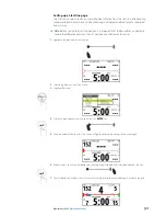
Страница 28: ...m the timer counter will show Minutes Seconds mm ss with the hours shown in the top right hand corner of the display Countdown timer To count down to a race start a time value can be set in the Set start value field in the Race Timer setup menu Set start value 1 Select the Start Time field 2 Use the UP DOWN keys to set the desired number 3 Press the ENTER key to move to each consecutive number 4 Pre...

Страница 29: ...chronize the time up or down to the nearest full minute Reset Selecting Reset will reset the timer to the start value If the timer was running it will continue to run from the start value Rolling timer Selecting Rolling timer will restart the countdown timer every time it reaches zero It will continue to do this until the timer is stopped Auto start trip Selecting Auto trip start will enable the T...

Страница 30: ...is is indicated with a circular symbol If the man over board event is activated via an AIS SART then this position will update via the AIS SART signal The GPS longitude and latitude co ordinates of the last known position are shown in the top left of the screen with the bearing and range MOB waypoint data listed below If you have an H5000 CPU on the network the CPU will perform dead reckoning calc...

Страница 31: ...lay will show the word OFF Remote displays The remote display page can be accessed from the Settings menu Here all HV Displays will be listed by size Any displays that are not present on the network will be greyed out To change what data is shown on a HV display highlight the display in this menu press the ENTER key and select the required data type from those listed Configuring an HV display From...

Страница 32: ... symbol next to the alarm in the alarm list will indicate that the alarm is on Note It is possible to enable disable all alarms by selecting the Alarms Enabled field from the Alarms menu Alarm settings 1 Press MENU on an alarm that requires parameters to be set will take you to the Enabled Set limit menu 2 Select Set limit 3 Set the required alarm parameter 4 Press the PAGE key once you have finishe...

Страница 33: ...wledging an alarm An alarm is acknowledged by pressing the ENTER key This will remove the alarm notification and silence the alarm from all units that belongs to the same alarm group A reminder will reappear at given intervals for as long as the alarm condition exists Note An alarm received from non B G units on the network must be acknowledged on the unit generating the alarm Alarm history The ala...

Страница 34: ...peed With Dynamic Damping the damping value applied to boat speed will reduce to almost zero during conditions when the data is changing rapidly The boat speed damping value is set in seconds to a steady state value the Dynamic Damping is set to a value between 0 off and 9 maximum the higher the value the more sensitive the boat speed is to rates of change and the quicker the damping value is lower...

Страница 35: ...istance traveled via GPS input Note Trip log 2 requires a compatible GPS connected to the network 1 2 3 4 No Description No Description 1 Trip distance 3 Trip time 2 Average speed 4 Maximum speed Note Correctly calibrated boat speed is essential for accurate trip records Log Shows total miles run from installation This is based on distance over the water ...

Страница 36: ...enus and confirm selections 4 DOWN Selects the lower half of the display to change variables scrolls through menus and variables increases decreases values 5 MENU LIGHTS Used to enter the Settings menu and scroll through the menu options Long press enters the lights settings page Display information 11 3 1 7 6 9 10 8 12 13 3 1 4 2 5 2 No Description No Description 1 Data variable name 8 Alarm Warni...

Страница 37: ...t data page to the next page in the cycle Note Pressing the PAGE key will change the data pages in sequence and in continuous rotation from pages 1 to 5 Edit data page contents You can edit any of the five data pages so that they display the specific boat data that you require Page data editing Select the page you wish to edit Press the UP key to select the top data field or the DOWN key to select th...

Страница 38: ...count up from zero to record the elapsed time Note Once the countdown timer reaches zero it will start counting up showing the elapsed time from zero The timer will continue to count until it is stopped Set Sets the value of the timer MENU Once set is selected use the directional keys to set the required time Note The timer can only be set to whole minutes Start Starts the timer If a time value is...

Страница 39: ...et via the race display to show a single variable Configuring remote display data Select the remote menu then select the remote display e g 20 20 HV you wish to configure Note The remote display will flash on and off to indicate it has been selected for editing by the race display MENU x2 Use the UP DOWN and ENTER keys to navigate to a variable and select the variable to display Exit by pressing the ...

Страница 40: ...ress the ENTER key MENU Trip log There are two recorded trip logs Trip log 1 records distance traveled through the water trip log 2 records distance traveled via GPS input Note Trip log 2 requires a compatible GPS connected to the network Start trip log MENU x3 Stop trip log MENU x3 Reset trip log Alarms When alarms are set to On the race display will show alarm messages when predefined alarm param...

Страница 41: ...sion This will remove the alarm notification text light and sound from all units on the network A reminder will reappear at given intervals for as long as the alarm condition exists x2 Diagnostics The diagnostic pages show details of the display instance number software version LCD test and reset options To access the diagnostic pages press and hold the MENU key when you power on the display Use th...

Страница 42: ...e display back to the default speed and depth page User reset Resets page configuration to their default settings All other settings will remain unchanged Select user reset press the ENTER key The display will show complete once finished LCD segment test When the LCD segment test page is selected the display will automatically begin the LCD test This is a visual test that needs to be performed by th...

Страница 43: ...he light settings in sequence It is the responsibility of the user to visually check the light levels Instance The display instance is a number that can be set as a reference for the user to distinguish between different displays By default the display instance is set to zero Voltage Shows the current voltage supply to the display ...

Страница 44: ...IGHT Changes target course 10º Starboard 3 1º COURSE CONTROL STARBOARD 1º RIGHT Changes target course 1º Starboard Activates Non Follow Up NFU mode when in Standby mode Enter menu 4 10º COURSE CONTROL PORT 10º LEFT Changes target course 10º Port 5 1º COURSE CONTROL PORT 1º LEFT Changes target course 1º Port Activates Non Follow Up NFU mode when in Standby mode Exit menu 6 STBY Disengages the autop...

Страница 45: ...o take manual control of the helm Warning In Standby mode pressing either of the 1º directional keys will engage the autopilot in Non Follow Up mode Menu navigation Single press of the MENU key will open the Main menu Note Whilst navigating the menu system If no selection is made after 10 seconds the screen will revert to the autopliot status screen Key Action 1º RIGHT Opens highlighted menu optio...

Страница 46: ...evert to Auto mode Wind W Steers the boat to maintain the set wind angle Press MODE key to enter to Auto mode Press MODE key again to revert to Wind mode Heading Speed True Wind Angle Press Hold 3 sec to enter mode menu then select required mode NoDrift ND Steers the vessel on a straight bearing line by compensating for drift Heading Position Navigation N Steers the boat to a specific waypoint loca...

Страница 47: ...ress the 1º RIGHT key to confirm Note The mode selection menu will time out after a few seconds Whichever mode is highlighted at this time will be selected 2 sec Non Follow Up mode Whilst in Standby mode pressing any of the 1º LEFT RIGHT keys will move the rudder to your desired angle and change the autopilot mode to Non Follow Up Non Follow Up mode allows you to control the rudder position manuall...

Страница 48: ...n the Setup Sailing menu The tack gybe time is also related to the speed of the boat to prevent excessive loss of speed during a tack Note The autopilot will temporarily add a 5 degree bear away on the new tack to allow the boat to pick up speed After a short period the wind angle will return to the set angle If neither tack gybe or cancel is selected the tack gybe pop up will close after 10 secon...

Страница 49: ...el 0 0 Setting the depth offset displays depth readings from directly below the keel or propellers of the boat or from the waterline to the seabed This makes it easier to see the available depth taking into account the draught of the boat The offset value to be entered should represent the distance between the face of the depth transducer and the lowest part of the boat below the waterline or the di...

Страница 50: ...e calibration field to exit 6 Select OK 7 Press ENTER to confirm and exit The offset will then be set to the desired value and the display will return to the calibration page Note If the calibration offset value fails an error message will appear Setting offset failed Check sensor connection and source selection and retry Boat speed Speed calibration is necessary to compensate for hull shape and paddle...

Страница 51: ... effect from wind or tidal current 1 Bring the boat up to cruising speed above 5 knots 2 Select Auto correct on the Calibrate boat speed page 3 When the calibration is completed the Boat speed calibration scale will show the adjusted percentage value of the boat speed 4 Select OK once complete to confirm correction and exit Manual adjustment of boat speed Adjust the boat speed manually by selecting ...

Страница 52: ...nce reference over 2 When the boat gets to the predetermined starting position of the distance reference calculation start the calibration timer 3 As the boat passes marks A and B on each run instruct the system to start Start Run and stop Stop Run and finally OK to end calibration End Cal Runs 4 After the last run is completed and OK has been selected Select save to store the calibration 5 A pop u...

Страница 53: ...ch sensor individually by selecting Port or Starboard boat speed from the calibration menu Note To enable dual sensors see Dual sensor support Measured sources for more information Note These options can be set via the H5000 Calibration menu on a compatible B G Multi Function Display MFD Heel correction Edit the heel correction table to improve the accuracy of boat speed data when the boat is heel...

Страница 54: ...between boat speed sensors The CPU can handle sensor switching in a variety of different ways Change this setting via the Switch dialog in the boat speed calibration menu Switch option Description MWA Uses the Measured Wind Angle MWA to determine the current tack Port tack Use starboard sensor Starboard tack Use port sensor Heel Uses the heel of the vessel to determine whether to use the port or st...

Страница 55: ...een wind sensors The CPU handles sensor switching automatically MHU Wind Sensor Sensor priority MHU 1 Wind sensor 1 Used when the measured wind angle is less than 90º on MHU 1 MHU 2 Wind sensor 2 Used when the measured wind angle is greater than 90º on MHU 1 Environment Sea Air Temperature Barometric pressure If a suitable sensor is fitted the system will monitor the current sea air temperature and...

Страница 56: ...cord the wind angle then repeat the process on a port tack Divide the difference between the two recorded numbers and enter this as the wind angle offset 33º 27º WIND Starboard Tack Port Tack Starboard tack 33º Port tack 27º Difference 33º 27º 6º Offset 6º 2 3º If the starboard apparent wind angle is greater than the port angle then divide the difference by 2 and enter this as a negative offset If the p...

Страница 57: ...uired in conjunction with a CPU running Hercules level software or greater to use this feature TWA TWS Correction tables The TWA and TWS Correction tables receive their information from the H5000 CPU This information is not stored in the CPU Note TWA TWS correction tables can also be adjusted from the webserver and the Zeus family MFDs Editing a correction table 1 Highlight the field that requires ...

Страница 58: ...True Wind Speed errors are seen from sailing upwind to downwind This is due to the acceleration of the airflow over the top of the mast and around the sails when sailing downwind 10 is the default value for TWA calibration Monitoring the change in True Wind Speed from close hauled to broad reaching will enable further refinement of this calibration value Auto Calibration via webserver It is possible...

Страница 59: ...nce between the known source and the currently displayed heading Enter this value as the offset in the compass heading field as a plus or minus number up to 180º Magnetic variation Adjust how the system handles magnetic variation Auto Receives variation data from a network source Manual If variation is not available enter a value manually Use COG as heading If heading data is not available from a co...

Страница 60: ...ce memory card USB stick that is compatible with the MFD 2 Place the device into the media slot on the MFD 3 Find the polar file via the Files folder on the Tools page 4 Copy the file from the portable media to the Polars directory 5 The new Polar file will now be available via the Polars menu of the H5000 Calibration page Editing polar tables 1 Open the table you wish to edit 2 Select the number and...

Страница 61: ...ed devices The data sources are normally configured at first time turn on It should only be necessary to update this data if a new source is added source is missing sensor failure source has been enabled disabled sensor replaced or a network reset Auto select The Auto select option will look for all sources connected to the instrument system If more than one source is available for each item the dis...

Страница 62: ...e selection below for more information Manual source selection If more than one source is available for an item the preferred source may be selected manually As an example the following illustrations show how the compass source is changed Select the preferred data source The selected source will be indicated by a tick in the check box Device list Shows a list of all devices connected to the Networ...

Страница 63: ...ol parameter settings in groups of units By assigning several units to the same group a parameter update on one unit will have the same effect on the rest in that group Note All groups are shipped from the factory set to Default Units Set the preferred unit of measurement you want data to be displayed in Note This can be performed via a Graphic Display Webserver or one of the Zeus family of MFDs ...

Страница 64: ...decimal places sea temperature will be displayed in 0 to 2 Language Set your preferred language for the display Note This is not a network function You will need to change all displays separately Note Once the required language is selected the unit will automatically restart and continue with step 2 of the startup wizard Time From the time menu you can set the preferred time date format and local ...

Страница 65: ...store defaults Restore Defaults has the option to wipe all settings or partial settings out of the Graphic Display Select the data from the list that you wish to delete Note This is not a network function This will only reset and delete history on the display that Restore defaults is selected on Global reset The global reset will reset all settings in all displays along with performing a network r...

Страница 66: ...66 System setup H5000 Operation Manual About Shows the device information and software version currently installed on the display Press the ENTER key to navigate back to the menu ...

Страница 67: ...s been enabled disabled sensor replaced or a network reset Note Source selection can also be performed by a Graphic Display Webserver or one of the Zeus family of MFDs Auto selection The Auto select option will look for all sources connected to the network If more than one source is available for each item the display will automatically select from the internal device priority list Manual source s...

Страница 68: ... rudder speed to be different from the one automatically set in the rudder test Rudder deadband The rudder deadband function is adaptive and is continuously updating It prevents the rudder from hunting and the adaptive function optimizes the deadband to the speed of the boat and the load on the rudder Note If the auto setting does not perform properly due to high inertia from the wheel it can be ad...

Страница 69: ...nsors Boat length Set the length of the vessel Press the 1º LEFT key to return to the dockside menu Drive voltage Select the drive voltage 12 or 24 Volts Press the 1º PORT key to return to the dockside menu Rudder calibration Make sure the rudder feedback unit is installed and aligned as per it s installation manual The rudder calibration will set the correct relationship between the physical rudd...

Страница 70: ...he rudder to midship position and confirm This will adjust an incorrect reading caused by misalignment of the rudder feedback unit Rudder Test Note If the boat uses power assisted steering it is important that the engine or electric motor used to enable the power assist steering be turned on prior to this test Warning Stand CLEAR of the wheel and do not attempt to take manual control of the wheel d...

Страница 71: ...or moderate sea conditions For displacement boats use a speed that is approximately half the normal cruising speed i e if cruising speed is 10 knots perform the Autotune at about 5 knots Select Autotune to begin the tuning process Press 1º RIGHT to confirm Autotune After the Autotune has been completed the rudder must be controlled manually as the autopilot has returned to Standby mode The Automati...

Страница 72: ...rameter that counteracts the effect of the boat s turn rate and inertia For a short time period it is superimposed on the proportional rudder response caused by the heading error It may sometimes appear as if it tends to make the rudder move to the wrong side counter rudder The best way of checking the value of the Counter Rudder setting is when making turns The figures illustrate the effects of vari...

Страница 73: ... features can be accessed via the Main menu Wind mode Select what wind function the autopilot will use when in wind mode Auto In auto if the AWA is 60º Wind mode will use apparent wind 61º Wind mode will use TWA True Apparent True Polar Note The current selection will be highlighted when you enter the menu Gust response Effects how the autopilot will react to rapid changes in heel angle caused by g...

Страница 74: ...ntrols the rate of turn tack time when performing a tack in wind mode Range Change per step Default Units 2 50 1 12 Second Tack angle Controls the angle that the boat will tack to between 50º 150º Note Only works in Auto mode Range Change per step Default Units 0 180º 1 100º Degrees Heel compensation Heel compensation provides protection against roll induced broaching in heavy seas or high gust co...

Страница 75: ... counter environmental changes Recovery Recovery Mode allows the user to set the sensitivity to course errors and how the autopilot will react to unexpected events for example sudden wave or wind shifts This function allows the autopilot to instantaneously increase the steering response to its maximum setting Perf 5 and make a rapid recovery The Recovery Mode will automatically switch off after 15 ...

Страница 76: ...ty control 0º to 20º Transition speed The speed in knots that the vessel will transfer from displacement to plaining mode Speed source The Autopilot will automatically prioritize which speed source it uses Automatic speed source priority 1 Boat speed Paddle wheel sensor 2 Speed Over Ground SOG GPS sensor Only used if there is no boat speed source Manual speed source If neither boat speed or SOG da...

Страница 77: ...e lighting group on the display All units in the selected lighting group will mirror each others light settings Default setting is Network Light level adjustment Press the MENU key for 3 seconds to access the backlight level screen The MODE key will increase the brightness level the MENU key will decrease the brightness Note Brightness level 1 10 The light level selection times out after 2 seconds...

Страница 78: ...78 Autopilot setup H5000 Operation Manual Key beeps Enable disable H5000 Pilot Controller key beeps Software info H5000 Pilot Controller serial number Software version Software release date ...

Страница 79: ... directly to the H5000 CPU via an ethernet cable or wirelessly via a WiFi 1 router Direct via Ethernet Connect a computer directly to the H5000 CPU via an ethernet cable 1 Connect device to the H5000 CPU via the ethernet port 2 Open web browser on the connected computer or device 3 Type the IP address 192 168 0 2 into the web browser address bar Note Unit will attempt to select a DHCP server for 2...

Страница 80: ...b If it says Websocket Not Connected then check the H5000 CPU and router power and connections Wireless via a WiFi 1 router Connect wireless devices to the H5000 CPU via a WiFi 1 router WIFI 1 WiFi 1Router Note To connect the WiFi 1 router to the H5000 CPU an Ethernet to RJ45 converter cable is required Part No 000 10438 001 WIFI 1 12V ...

Страница 81: ...der H5000 CPU info Make a note of this IP address 3 Open web browser on the connected computer or device 4 Type the H5000 CPU IP address into the web browser address bar Note Unit will attempt to select a DHCP server for 2 minutes after power on If the server is not detected the unit will revert to IP address 192 168 0 2 Once connected correctly the Webserver will show Websocket Connected in the t...

Страница 82: ...Configure setup Boat Speed Configure setup Measured Wind Configure setup True Wind Configure setup Polar Tables Configure setup VMG Targets Configure setup Heel Configure setup Trim Configure setup Leeway Configure setup System Settings Data settings Units System units Damping Damping values Alarms Configure setup alarms User data Label user linears remote channels Device List All devices on network CPU Bac...

Страница 83: ...r 2 Select CPU Software tab 3 Check feature level for current software version 4 Purchase desired CPU level from an approved B G dealer Note The CPU Bar Code Serial Number will be required to generate the unlock code This number can be found under CPU Information on the software page 5 Select Unlock next to the CPU level your unlock code relates to 6 Enter the unlock code in the dialog box 7 Selec...

Страница 84: ...84 Webserver H5000 Operation Manual Webserver help files Selecting the help tab located in the top righthand corner of the screen will show the help files related to the current page or feature ...

Страница 85: ...ality which includes Hydra functions Indicates that the information listed relates to Performance processor functionality which includes Hydra Hercules functions Please contact your local dealer if you wish to upgrade your processor A list of B G approved dealers can be found at www bandg com Aft depth Aft Depth is an auxiliary Depth function which allows the system to display two Depth readings o...

Страница 86: ...ll provide the correct data Calibration of analog linear functions For all linear functions it is necessary to set the Type value see table below Description Function declared 0 to 10 Linear None 0 to 100 Linear None 0 to 1000 Linear None x2 y1 y2 x1 x1 Analog Volts 1 y1 Analog value 1 x2 Analog Volts 2 y2 Analog value 2 Note Analog linear channel is the channel on the display where the data is se...

Страница 87: ...ue Wind Correction data Raw wind speed data from the masthead unit is displayed as Measured Wind Speed Variable name default Function name App Wind Speed AWS AWS Units kph mph Alarms N A Calibration Hz Kt Damping 0 9s Note The calibration values are factory set based on wind tunnel tested sample units and it is not recommended to change these The option to change them exists for advanced users who...

Страница 88: ...the power supply voltage measured internally by the CPU Variable name default Function name Battery Volts BATT BATTERY Units V Alarms High Low Calibration Offset set to known value Damping N A Bearing to waypoint Bearing To Waypoint displays the bearing from the yachts current position Boat Position to the current active waypoint This function repeats information received from a position fixing devi...

Страница 89: ...eats information received from a position fixing device e g GPS via a NMEA input Variable name default Function name Boat Position POS N A Units ddº mm mm dddº mm mm Alarms N A Calibration N A Damping N A Boat speed Boat Speed displays the speed of the boat through the water Accurate calibration of Boat Speed is critical to the overall performance of the system On larger format displays an indicato...

Страница 90: ...0 0 the voltage is automatically recorded and can be noted from VOLTS 1 if required Position the boom at its highest normal position set POINT 2 to be 5 0 the voltage is automatically recorded and can be noted from VOLTS 2 if required After calibration check that the value displayed for Boom Position is positive if the boom is high of the furling position zero at the furling position and negative ...

Страница 91: ...positive Variable name default Function name Canard Can CANARD Units Degrees Alarms N A Calibration Position 1 known value 1 Volts 1 automatically recorded Position 2 known value 2 Volts 2 automatically recorded Damping N A Course Course is a combination of Heading and Leeway and gives a more accurate number than heading alone on which to base tacking angles etc In the absence of a Heel Angle sens...

Страница 92: ...daggerboard is fully down and a negative value as it is raised If Daggerboard is not available in the menu structure it is necessary to determine the linear input in use and configure it correctly Refer to installtion information Position the daggerboard in the fully extended position set POINT 1 to be 0 0 the voltage is automatically recorded and can be noted from VOLTS 1 if required Position the ...

Страница 93: ... 2 3 4 5 6 DeadReckoning No Description 1 Starting point 2 Course made good 3 Actual course sailed 4 Distance made good 5 Course reads 213º Distance reads 17 8 miles 6 Tide vector D R calculations are based on the Course function therefore if a Heel Angle sensor is fitted the D R data can be corrected for Leeway System requirements N A Connection N A Variable name default Function name D RCourse D ...

Страница 94: ...ance from the yachts current position Boat Position to the current active GPS waypoint Variable name default Function name Distance to waypoint WPT DIST Units Nm Alarms N A Calibration N A Damping N A Ground wind Direction Wind direction relative to the ground at a fixed position Variable name default Function name Ground wind direction GWD Units ºM ºT Alarms N A Calibration N A Damping N A Ground ...

Страница 95: ...ollowing after tacking to the same TWA on the other tack Note This function does not take any tidal effects into consideration Variable name default Function name Heading Opp Tack OppT OPP HDG Units ºM ºT Alarms N A Calibration N A Damping N A Heel angle The Heel Angle function displays the port starboard inclination of the yacht Heel data is used to calculate other functions including Leeway and C...

Страница 96: ...o starboard set POINT 2 to be a value equal to the angle of the keel in this example 40 0 the voltage is automatically recorded and can be noted from VOLTS 2 if required Variable name default Function name Keel Angle Keel KEEL ANG Units Degrees Alarms N A Calibration Position 1 Known Value 1 Volts 1 Automatically Recorded Position 2 Known Value 2 Volts 2 Automatically Recorded Damping 0 9s Latitud...

Страница 97: ...nt Webserver to be entered in the webserver User User configurable linear Note Rename the user channel via the Webserver Variable name default Function name Linear n LIN n LINEAR n Units N A Alarms N A Calibration Type see table below Minimum value at 0V Maximum value at 5V Damping N A Local time Displays local time from an interfaced position fixer Ensure that your position fixer is configured to app...

Страница 98: ...the basic offset value for alignment Measured Wind is not used whilst sailing but is a useful function for checking the operation and alignment of the wind instruments before additional corrections are applied to the data during the calculation of the True Wind and Apparent Wind Variable name default Function name Measured Wind Angle MWA MWA Units Degrees Alarms N A Calibration Offset Damping N A Me...

Страница 99: ...ed Should the leg be upwind or downwind rather than free the H5000 calculates the data using the Target TWA on the favoured tack this situation is indicated on the display by the position of a small bar at the top upwind or bottom downwind of the digits Variable name default Function name Next Leg AWA NL AWA NL AWA Units Degrees Alarms N A Calibration N A Damping N A Next leg apparent wind speed S...

Страница 100: ...wind for the current wind condition Sometimes particularly downwind it is easier to try to sail to a wind angle rather than to the Target True Wind Angle TWA The accuracy of this function will depend on how accurate the polar tables are for your boat Variable name default Function name Optimum Wind Angle OPT WA OPT TWA Units Degrees Alarms N A Calibration N A Damping N A Polar Boat Speed Polar Boa...

Страница 101: ...used by Hercules Motion for wind correction This function is shown for diagnostic purposes only Note Also see Roll Rate Variable name default Function name Pitch Rate PITCH Units Degrees per Second Alarms N A Calibration N A Damping N A Rate of Turn Rate of Turn is damped Yaw Rate for display Variable name default Function name Rate of Turn TURN RTE Units Degrees per Second Alarms N A Calibration ...

Страница 102: ...e Useful for assessing the balance of the yacht especially upwind Variable name default Function name Rudder Angle Rud RUDDER Units Degrees Alarms N A Calibration Offset Damping N A Speed over ground Speed Over Ground SOG displays the current speed of the yacht relative to land rather than the water Variable name default Function name SOG SOG Units kt Alarms N A Calibration Offset Damping 0 9 Stored...

Страница 103: ...chieved derived from the polar table Variable name default Function name Target TWA TG TWA TARG TWA Units Degrees Alarms N A Calibration N A Damping N A Temperature Air Air Temperature AIR displays the current temperature read via the sensor Variable name default Function name Air Temperature AIR AIR TEMP Units ºC ºF Alarms High and Low Calibration Offset Damping N A Temperature Aux Displays the cu...

Страница 104: ...er Importantly the damping on this function is adjustable in rapidly changing tidal situations you need to lower the damping down as far as possible to be able to see the changes quickly However in stable conditions probably offshore averaging the data over a longer time will normally give a more stable accurate figure In addition note that particularly frequent manoeuvring can produce unreliable fig...

Страница 105: ...A Calibration N A Damping N A Time to waypoint Displays time until arrival at the active waypoint at the current speed and course Variable name default Function name Time to Waypoint t WPT TTW Units hh mm ss Alarms N A Calibration N A Damping N A Trip log The Trip Log records the distance travelled through the water The value displayed is the distance in nautical miles travelled from the time the ...

Страница 106: ...e the linear input in use and configure it correctly Position the tab centrally set POINT 1 to be 0 0 the voltage is automatically recorded and can be noted from VOLTS 1 if required Position the tab at a known angle e g 10º starboard set POINT 2 to be this angle e g 10 0 the voltage is automatically recorded and can be noted from VOLTS 2 if required By convention if the tab is to starboard of the c...

Страница 107: ...te True Wind data True Wind data is used to back calculate Apparent Wind data as shown in the vector triangle below 1 2 3 4 5 6 7 WindTriangle No Description 1 True Wind Speed 2 True Wind Direction 3 True Wind Angle 4 Apparent Wind Speed 5 Heading 6 Apparent Wind Angle 7 Wind Variable name default Function name True Wind Angle TWA TWA Units Degrees Alarms Sector Calibration True Wind Correction Ta...

Страница 108: ...ilable Hercules 2 3 1 TrueWindDirection No Description 1 Heading 240º 2 True Wind Direction 280º 3 True Wind Angle 40º Variable name default Function name True Wind Angle TWA TWA Units Degrees ºm ºT Alarms N A Calibration True Wind Correction Tables AutoCal TWA correction routine Damping 0 9s True Wind Speed True Wind Speed TWS is the speed of the wind measured relative to the water surface Variab...

Страница 109: ... Made Good VMG is the component of Boat Speed in the direction of the True Wind VMG is used for monitoring performance of the yacht on upwind or downwind legs as the data considers both Boat Speed and True Wind Angle therefore indicating whether sailing slower but closer to the wind is better than sailing faster but at a wider TWA 1 2 8 3 4 5 6 7 UP WIND DOWN WIND CalculationofVMG No Description 1...

Страница 110: ...n the direction of the waypoint Normally SOG is the speed reference used as the data is provided by the position fixer 1 2 3 4 OptimumVMGtoMark No Description 1 True wind direction 2 Direction of new mark 3 Optimum VMC course 4 Polar curve Variable name default Function name VMG Waypoint VMC VMG CSE Units kt Alarms N A Calibration N A Damping N A ...

Страница 111: ...Wind Angle downwind 4 Target boat speed upwind 5 Maximum VMG upwind 6 Maximum VMG downwind 7 Target boat speed downwind The Polar Table describes the performance of the boat in all conditions of True Wind Speed and Angle The Boat Speed is plotted radially against the True Wind Angle for each True Wind Speed in turn The result is a Polar Performance Curve shown above this shows the boat speed plott...

Страница 112: ... for non wing masts to align the rig for minimum drag Variable name default Function name Mast MWA WAM MAST AWA Units Degrees Alarms N A Calibration N A Damping N A Yaw rate Yaw Rate is the turn rate of the boat in degrees second Note Yaw rate is displayed on the system for diagnostic purposes only It is also used internally by the autopilot Variable name default Function name Yaw Rate Yaw YAW RAT...

Страница 113: ...4 60 5 67 6 67 7 38 7 80 8 10 8 28 8 42 130 1 90 3 50 4 90 6 00 6 87 7 51 7 96 8 21 8 36 8 48 120 1 97 3 65 5 08 6 30 7 06 7 65 8 00 8 30 8 43 8 53 110 1 99 3 76 5 26 6 39 7 11 7 65 7 96 8 19 8 40 8 50 100 1 98 3 85 5 40 6 39 7 10 7 59 7 87 8 03 8 30 8 39 90 2 00 3 90 5 45 6 31 7 02 7 45 7 74 7 88 8 11 8 18 80 2 02 391 5 40 6 27 6 88 7 30 7 61 7 73 7 89 7 95 70 2 10 3 83 5 22 6 18 6 79 7 22 7 48 7...

Страница 114: ...0 0 0 0 0 2 20º Heel 0 0 0 0 0 0 0 0 0 0 0 0 0 0 True wind angle correction Column 0 1 2 3 4 5 6 Row TWS 0 5 10 15 20 25 30 0 40º TWA 0 7 0 3 0 2 5 4 5 6 5 8 0 1 90º TWA 0 2 0 1 0 0 0 1 0 1 0 1 5 2 165º TWA 0 4 0 3 0 1 0 1 0 1 0 2 0 True Wind Speed correction Column 0 1 2 3 4 5 6 Row TWS 0 5 10 15 20 25 30 0 Correction 0 0 6 1 2 1 8 2 4 3 0 3 6 Downwind correction angle for TWS Column 0 1 2 3 4 5 ...

Страница 115: ...e connectors should be checked by visual inspection only Push the connector plugs into the connector if the connector plugs are equipped with a lock ensure that this is in the correct position Software upgrades Please contact your local dealer if you wish to upgrade your processor A list of B G approved dealers can be found at www bandg com Through hull housings Keep the screw threads of through h...

Страница 116: ...for cleanliness and sprayed with a water inhibitor such as WD40 The outer casing of the connector should also be smeared with silicone grease The masthead unit must never be oiled The bearings are of the sealed pre lubricated type and any additional oil may cause chemical breakdown of the existing lubricant Any scratch marks or corrosion on masthead unit spar should be rubbed clean with a soft clo...

Страница 117: ...www bandg com 988 10630 002 ...

Отзывы: