background image

C

Co

om

mp

plle

ette

ed

d  IIn

ns

stta

alllla

attiio

on

n

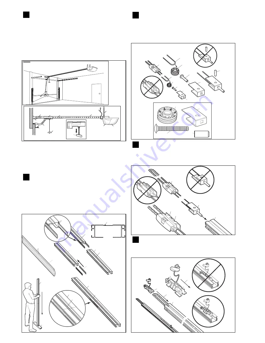
As you proceed with the assembly, installation and adjustment
procedures in this manual, you may find it helpful to refer back to
this illustration of a completed installation.

4

(1) 

Cable Pulley Bracket

(2)

Trolley

(3)

Chain/Cable Assembly

(4) 

Rail

(5) 

Hanging Bracket

(6)

Power Cord

(7) 

Opener

(8) 

Light Lens

(9) 

Manual Release
Rope & Handle

(10) 

Door Arm

(11)

Door Bracket 

(12)

Header Bracket

ASSEMBLY SECTION

Assemble Rail 

Place Rail pieces (1) on a flat surface for assembly. Take special note
of the raised line on the Rail pieces (4) these lines MUST line up in
order for the Rail to fit together properly. All three Rail sections are
interchangeable. Slide Rail Braces (2) into slots on the sides of Rail.
Make sure small tabs on Rail Braces (3) are up against top lip of Rail.
Connect Rail by sliding other end of braces into next Rail. Be sure the
raised lines that run down Rail sections (4) line up. Tap Rail assembly
(5) on a piece of wood (6) until Rail sections are flush. Repeat for final
Rail section.

5

Assemble Cable Pulley Bracket

Insert Carriage Bolt (1) though square hole in Cable Pulley Bracket (4).
Remove Chain/Cable assembly (3) from carton. Wrap Cable around
Cable Pulley (2) and insert Pulley into Bracket (

NOTE:

Make sure the

Bracket is assembled in position shown).

Slide pin (5) through holes in

Cable Pulley Bracket and Cable Pulley. 

NOTE: 

Trolley with Magnet (6)

MUST be installed in the position shown.

6

1

2

3

4

6

5

9

10

12

11

8

7

NOTICE

9

4

1

1

1

4

4

1

5

5

4

6

2

2

4

5

4

3

3

1

2

5

4

4

3

1

2

5

1

2

4

3

6

Insert Chain/Cable into Rail

Slide Cable Pulley Bracket (1) into Rail assembly (3), be sure to insert
Cable Pulley Bracket as shown. Push Cable Pulley Bracket toward
front of Rail and slide Inner Trolley (2) into Rail assembly. Magnet (4)
MUST be installed in position shown or unit will not function properly.

7

1

2

3

2

4

Attach Trolley to Rail 

Turn Rail assembly over. Slide Outer Trolley (1) into Rail assembly (2),
be sure the end with Door Arm Hole (3) is heading in direction of door
(4). Slide Outer Trolley down Rail until it engages with Inner Trolley.

8

1

2

1

3

4

4

Содержание Econolift ML500

Страница 1: ...e to comply with the installation instructions and the safety warnings may result in serious personal injury and or property and remote control opener damage Please save these instructions for future reference Econolift Econolift SECTIONAL TILTING GARAGE DOOR OPENER ML500 Econolift Sectional Tilting Garage Door Opener ...

Страница 2: ... injury from a closing garage door may result from misuse of the opener Activate opener ONLY when the door is in full view free of obstructions and opener is properly adjusted No one should enter or leave the garage while the door is in motion Do not allow children to play near the door Use manual release only to disengage the trolley and if possible ONLY when the door is closed Do not use the red...

Страница 3: ...ssembly 5 on a piece of wood 6 until Rail sections are flush Repeat for final Rail section 5 Assemble Cable Pulley Bracket Insert Carriage Bolt 1 though square hole in Cable Pulley Bracket 4 Remove Chain Cable assembly 3 from carton Wrap Cable around Cable Pulley 2 and insert Pulley into Bracket NOTE Make sure the Bracket is assembled in position shown Slide pin 5 through holes in Cable Pulley Bra...

Страница 4: ...Bolts Mark length on ceiling starting at the Header Wall along this point is where the unit will be mounted Lift door to full open position rest opener on door Insert Square Head Screws A into Rail assembly B approximately 120mm from end of Rail near motor unit Slide Hanging Brackets on to Square Head Screws and secure Brackets with Nuts 5 In this process the Square Head Screws hook into slots on ...

Страница 5: ...r may result in serious personal injury from a closing garage door Repeat test once a month and adjust as needed Procedure Place a 40mm obstacle 1 laid flat on the floor under the garage door Operate the door in the down direction The door must reverse on the obstruction If the door stops on the obstruction it is not travelling far enough in thedown direction Move Close Limit closer to door When t...

Страница 6: ... 2 minutes when power is connected After 2 1 2 minutes it will turn off 21 1 Install Safety Infrared Beam Kit Optional See accessories After opener has been installed and adjusted optional IR beams can be installed Instructions are included with this device It uses an invisible beam which when broken by an obstruction causes a closing door to open and prevents an open door from closing and is stro...

Страница 7: ... installation instruction warning on page 1 Try a new battery If you have two or more remotes and only one operates review receiver programming procedures in Step 21 Is there a build up of ice or snow under door The door may be frozen to ground Remove any obstruction The garage door spring may be broken Have it professionally replaced 2 Remote has short range Is battery installed Try a new one Cha...

Страница 8: ... warranty is expressly instead of all other warranties express or implied including any implied warranty of merchantability or fitness for a particular purpose and notwithstanding any course of dealing between the parties or custom and usage in the trade to the contrary 8 No other liability Subject to the warranty in clause 3 and to clause 6 B D shall not be subject to nor incur and the purchaser ...

Отзывы: