6
Illustration # 8
90294_10-22-12
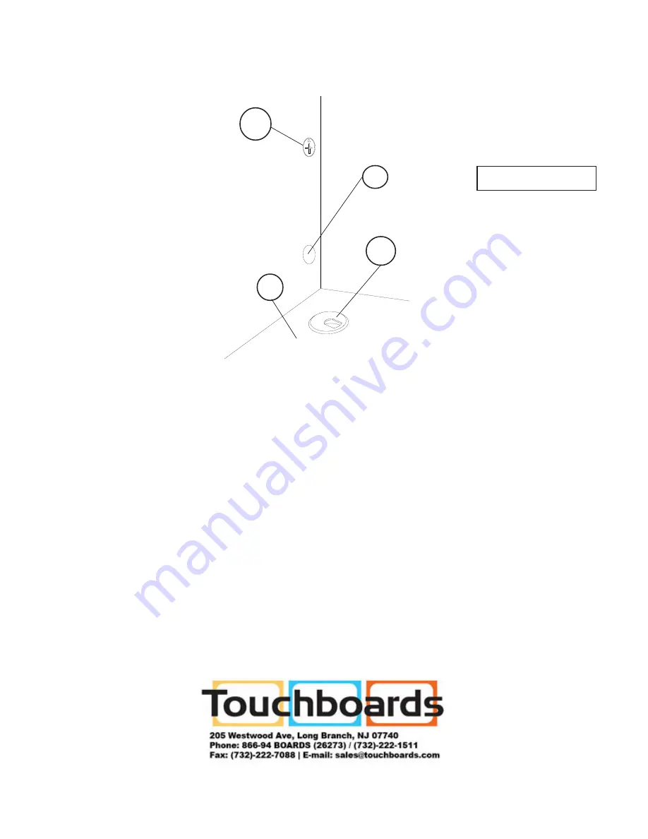
10.) Push in the Grommets (G) into the Top Panel (P-8) cut-out and in the Back Panel (P-7)
cut-out. Use the Stick-On Dots (I) to cover the Cams (D). See illustration #8.
D
I
P-8
G
Страница 1: ...789012345678901234567890121234567890123456789012345678901212345678901234 123456789012345678901234567890121234567890123456789012345678901212345678901234 123456789012345678901234567890121234567890123456...
Страница 2: ...y six months check all screws to be sure they are tight If parts are missing broken damaged or worn stop use of the product until repairs are made by your dealer using factory authorized parts Adjusta...
Страница 3: ...nto the bottom of one Insert Leg P 4 Place the Insert Leg P 4 into the bottom of the Left Back Upper Leg P 3 and secure at the same height as the Front Legs using two Screws A as shown in illustration...
Страница 4: ...s D into the large predrilled holes on the Left Wing Panel P 5 Make sure the arrow on the Cam is pointed to the small hole connecting hole in the edge Insert the Front Leg s Camposts B into the small...
Страница 5: ...7 and turn the Cams 90 degrees to lock the leg in place Repeat this Step to install the Right Back Leg to the Back Panel See illustration 6 D P 7 9 Slide the Top Panel P 8 and the Shelf P 9 in between...
Страница 6: ...6 Illustration 8 90294_10 22 12 10 Push in the Grommets G into the Top Panel P 8 cut out and in the Back Panel P 7 cut out Use the Stick On Dots I to cover the Cams D See illustration 8 D I P 8 G...