PANEL SHUTTER MOTOR UNIT
PANEL LIFTER START RELAY
E-119-379
LIFTER START RELAY
Switch/Coil
Part No.
Location on
Wire
Wire Color
Function
Diagram
No.
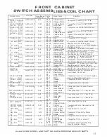
SHUTTER
E-119-379
A-17
70
Orange
. Energized thru start re.
circuit or
Motor
53-5
White-Yellow
anti-cheat circuit.
CAM #1
ASW-Cl-27
F-17
53-5
White-Yellow
(Carry Over) completes circuit to
A.
N.O.
30
Yellow
shutter motor.
Cam
l/1
ASW-C2-15
B-16
61-7
Brown-Red
Opens circuit to timer cams index,
B.
N.C.
48-13
Green-Black
while shutter is ooenine: or closin{T,
Cam
#1
ASW-C2-2
R-36
45-13
Green-White
Opens circuit to program control
C.
N.C.
21-3
Blue-Red
circuit while shutter is opening or
closing.
CAM #lX
ASW-Cl-27
F-33
30
Yellow
Completes coin lite circuit, when
A.
N.O.
52-13
White-Blue
shutter is open.
Cam
#lX
ASW-C2-15
E-25
50-5
White
When shutter is closed, completes
B.
N.C.
21-3
Blue-Red
after 5th ball timer step-up circuit,
also enables timer to reset thru "R"
Button.
Cam
.nx
ASW-C2-2
K-15
90
Grey
When shutter is open, sw. opens
c.
N.C.
Q-35
21-3
Blue-Red
winner circuit.
Cam #2
ASW-Cl-27
E-29
36-3
Yellow-Brown
When shutter is open, completes
A.
N.O.
31-3
Yellow-Red
circuit to Ball Lift Motor.
Cam #3
ASW-Cl-27
C-32
85-5
Black-White
When Shutter opens,
completes path
A.
N.O.
30
Yellow
to Unit Reset Coils.
Cam #3
ASW-Cl-28
C-6
90-10
Grey
When Shutter opens,
pulses trip bank
B.
N.O.
30
Yellow
reset motor.
CAM #4
ASW-Cl-27
Q-8
10-15
Red
When shutter
,
closes, completes cir-
A.
N.O.
21-3
Blue-Red
cuit to Magic Sq. control Circuit; &
Search Lock Circuit to be used after
4th Ball is shot.
Cam
#4
ASW-Cl-28
Q-4
15-11
Red-White
When shutter is closed completes
B.
N.O.
21-3
Blue-Red
timer circuit to B-4 & B-5 trips.
Cam
#4
ASW-C2-15
E-18
18-3
Red-Black
When shutter is open, completes cir-
C.
N.C.
45-8
Green-White
cuit to shutter motor.Will close shutter
if game is tilted.
Cam
#4
ASW-C2-2
D-18
18-3
Red-Black
When shutter is open, completes cir-
D.
N.C.
53-5
White-Yellow
cuit to run shutter motor thru timer
rlicc.
ALWAYS GIVE MCCEL ANO PART NC. WHEN CRCERING SERVICE PARTS
35


