background image

www.balluff.com

3

español

BTL5-P/I/L/M1-M _ _ _ _ -H/W(8) -S32/KA _ _ /K _ _

Sistema magnetostrictivo de medición de posición – Forma constructiva de varilla

Indicaciones para el usuario 

4

1.1  Validez 4
1.2  Símbolos y convenciones utilizados 

4

1.3  Volumen de suministro 

4

1.4  Homologaciones e identificaciones 

4

Seguridad 5

2.1  Uso debido 

5

2.2  Generalidades sobre la seguridad 

5

2.3  Significado de las advertencias 

5

2.4  Eliminación de desechos 

5

Estructura y funcionamiento 

6

3.1  Estructura 6
3.2  Funcionamiento 7
3.3  Número de sensores de posición 

7

Montaje y conexión 

8

4.1  Variantes de montaje 

8

4.2  Preparación del montaje 

8

4.3  Montar el BTL 

9

4.3.1  Recomendación de montaje para cilindros hidráulicos 

9

4.4  Conexión eléctrica 

10

4.5  Blindaje y tendido de cables 

11

Puesta en servicio 

12

5.1  Puesta en servicio del sistema 

12

5.2  Indicaciones sobre el servicio 

12

Datos técnicos 

13

6.1  Precisión 13
6.2  Condiciones ambientales 

13

6.3  Alimentación de tensión (externa) 

13

6.4  Señales de control 

13

6.5  Sensores de posición 

13

6.6  Medidas, pesos 

14

Accesorios 15

7.1  Sensor de posición 

15

7.2  Conectores y cables 

16

7.2.1  BKS-S32/S33M-00, libremente confeccionable 

16

7.2.2  BKS-S232/S233-PU-_ _, confeccionado 

16

Código de modelo 

17

Anexo 18

9.1  Conversión de unidades de longitud 

18

9.2  Placa de características 

18

Содержание Micropulse BTL5 Series

Страница 1: ...BTL5 P I L M1 M_ _ _ _ H W 8 S32 KA_ _ K_ _ deutsch Betriebsanleitung english User s guide fran ais Notice d utilisation italiano Manuale d uso espa ol Manual de instrucciones...

Страница 2: ...www balluff com...

Страница 3: ...Betriebsanleitung BTL5 P I L M1 M_ _ _ _ H W 8 S32 KA_ _ K_ _ deutsch...

Страница 4: ...www balluff com...

Страница 5: ...Anschluss 8 4 1 Einbauvarianten 8 4 2 Einbau vorbereiten 8 4 3 BTL einbauen 9 4 3 1 Einbauempfehlung f r Hydraulikzylinder 9 4 4 Elektrischer Anschluss 10 4 5 Schirmung und Kabelverlegung 11 5 Inbetr...

Страница 6: ...u bestellen 1 4 Zulassungen und Kennzeichnungen UL Zulassung File No E227256 US Patent 5 923 164 Das US Patent wurde in Verbindung mit diesem Produkt erteilt Mit dem CE Zeichen best tigen wir dass uns...

Страница 7: ...ignete Sicherheitsma nahmen treffen kann Der Betreiber hat die Verantwortung dass die rtlich geltenden Sicherheitsvorschriften eingehalten werden Insbesondere muss der Betreiber Ma nahmen treffen dass...

Страница 8: ...zone1 BTL5 KA _ _ BTL5 K_ _ BTL5 S32 Positionsgeber 2 1 1 Nicht nutzbarer Bereich 2 Nicht im Lieferumfang enthalten Nennl nge Messbereich 3 1 Aufbau Elektrischer Anschluss Der elektrische Anschluss is...

Страница 9: ...schwindigkeit fortschreitet Die zum Ende des Wellenleiters laufende Torsionswelle wird in der D mpfungszone absorbiert Die zum Anfang des Wellenleiters laufende Torsionswelle erzeugt in einer Abnehmer...

Страница 10: ...chmesser bei Einbau in einen Hydraulikzylinder 4 2 Einbau vorbereiten Einbauvariante F r die Aufnahme des BTL und des Positionsgebers empfehlen wir nichtmagnetisierbares Material Waagerechte Montage B...

Страница 11: ...Detaill sungen liegt in der Verantwortung des Zylinderherstellers Der Werkstoff des Gleitelements muss auf den Belastungs fall das eingesetzte Medium und die auftretenden Tempe raturen abgestimmt sei...

Страница 12: ...en zu Schirmung und Kabelverlegung auf Seite 11 Pin Adernfarbe P I L M 1 YE Gelb Init 2 GY Grau Start Stop 2 Flanke Start Stop Tri State 2 Flanke Tor Start Stop 1 Flanke 3 PK Rosa Init 4 RD Rot nicht...

Страница 13: ...en Magnetfelder Das Positionsmessystem ist ein magnetostriktives System Auf ausreichenden Abstand des BTL und des Aufnahme zylinders zu starken externen Magnetfeldern achten Kabelverlegung Kabel zwisc...

Страница 14: ...personal Sicherheitshinweise des Anlagen oder Systemher stellers beachten 1 Anschl sse auf festen Sitz und richtige Polung pr fen Besch digte Anschl sse tauschen 2 System einschalten 3 Messwerte und e...

Страница 15: ...N 60068 2 63 4 12 g 10 2000 Hz Schutzart nach IEC 60529 Stecker in verschraubtem Zustand IP67 Kabel IP683 2 6 3 Spannungsversorgung extern Spannung stabilisiert5 20 28 V DC Restwelligkeit 0 5 Vss Stro...

Страница 16: ...hl Wandst rke Stab bei 8 mm bei 10 2 mm 0 9 mm 2 mm Geh usebefestigung ber Gewinde M18 1 5 oder 3 4 16UNF BTL5 K_ _ BTL5 KA_ _ Kabelmaterial PUR cULus 20549 80 C 300 V internal wiring Kabeltemperatur...

Страница 17: ...temperatur 40 C 85 C Im Lieferumfang der Positionsgeber BTL P 1013 4R BTL P 1013 4S BTL P 1012 4R enthalten Distanzst ck 8 mm Material Polyoxymethylen POM Positionsgeber BTL5 P 4500 1 Elektromagnet Ge...

Страница 18: ...der gerade umspritzt konfektioniert M16 8 polig Unterschiedliche Kabell ngen bestellbar z B BKS S232 PU 05 Kabell nge 5 m Bild 7 5 20 66 Steckverbinder BKS S232 PU _ _ BKS S233 PU _ _ Steckverbinder g...

Страница 19: ...W M0025 M5500 Stabversion Befestigung H metrisches Befestigungsgewinde M18 1 5 O Ring Stabdurchmesser 10 2 mm W Zollgewinde 3 4 16UNF O Ring Stabdurchmesser 10 2 mm H8 metrisches Befestigungsgewinde M...

Страница 20: ...9 1 Umrechnungstabelle mm inch 1 inch 25 4 mm inch mm 1 25 4 2 50 8 3 76 2 4 101 6 5 127 6 152 4 7 177 8 8 203 2 9 228 6 10 254 Tab 9 2 Umrechnungstabelle inch mm 9 Anhang 9 2 Typenschild Bild 9 1 Typ...

Страница 21: ...User s Guide BTL5 P I L M1 M_ _ _ _ H W 8 S32 KA_ _ K_ _ english...

Страница 22: ...www balluff com...

Страница 23: ...4 1 Installation guidelines 8 4 2 Preparing for installation 8 4 3 Installing the BTL 9 4 3 1 Installation recommendation for hydraulic cylinders 9 4 4 Electrical Connection 10 4 5 Shielding and cabl...

Страница 24: ...gs UL approval File no E227256 US Patent 5 923 164 The US patent was awarded in connection with this product The CE Mark verifies that our products meet the requirements of the current EMC Directive T...

Страница 25: ...hazards and take appropriate safety measures The operator is responsible for ensuring that local safety regulations are observed In particular the operator must take steps to ensure that a defect in...

Страница 26: ...H M18 1 5 W 3 4 16UNF H 40 1mm W 2 0 04 Mounting surface Damping zone1 BTL5 KA _ _ BTL5 K_ _ BTL5 S32 Magnet 2 1 1 Unusable area 2 Not included in scope of delivery Nominal length Measuring range 3 1...

Страница 27: ...nent of the torsional wave which arrives at the end of the waveguide is absorbed in the damping zone to prevent reflection The component of the torsional wave which arrives at the beginning of the wav...

Страница 28: ...lic cylinder 4 2 Preparing for installation Installation note We recommend using non magnetizable material to mount the BTL and magnet Horizontal assembly For horizontal assembly with nominal lengths...

Страница 29: ...d end from wear Dimensioning of the detailed solutions is the responsibility of the cylinder manufacturer The slide element material must be suitable for the appropriate load case medium used and appl...

Страница 30: ...tart Stop 1st edge 3 PK Pink Init 4 RD Red Not used1 5 GN Green Start Stop 2nd edge Start Stop tri state 2nd edge Tor Start Stop 1st edge 6 BU Blue GND 7 BN Brown 20 28 V 8 WH White Not used1 1 Unassi...

Страница 31: ...ive earth conductor Magnetic fields The position measuring system is a magnetostrictive system Ensure that there is sufficient distance between the BTL holding cylinder and strong external magnetic fi...

Страница 32: ...the safety instructions of the equipment or system manufacturer 1 Check connections for tightness and correct polarity Replace damaged connections 2 Turn on the system 3 Check measured values and adju...

Страница 33: ...Vibration per EN 60068 2 63 4 12 g 10 2000 Hz Degree of protection per IEC 60529 Connector when attached IP67 Cable IP683 2 6 3 Supply voltage external Voltage stabilized5 20 28 V DC Ripple 0 5 Vpp C...

Страница 34: ...ial Stainless steel Rod wall thickness at 8 mm at 10 2 mm 0 9 mm 2 mm Housing mounting via threads M18 1 5 or 3 4 16UNF BTL5 K_ _ BTL5 KA_ _ Cable material PUR cULus 20549 80 C 300 V internal wiring C...

Страница 35: ...nt temperature 40 C 85 C Included in the scope of delivery for the BTL P 1013 4R BTL P 1013 4S BTL P 1012 4R Spacer 8 mm material polyoxymethylene POM BTL5 P 4500 1 magnet solenoid Weight Approx 90 g...

Страница 36: ...lded preassembled M16 8 pin Various cable lengths can be ordered e g BKS S232 PU 05 Cable length 5 m Fig 7 5 20 66 Connector type BKS S232 PU _ _ BKS S233 PU _ _ Angled connector molded preassembled M...

Страница 37: ...00 mm H8 W8 M0025 M1016 H W M0025 M5500 Rod version fastening H Metric mounting thread M18 1 5 O ring rod diameter 10 2 mm W 3 4 16UNF thread O ring rod diameter 10 2 mm H8 Metric mounting thread M18...

Страница 38: ...1 Conversion table mm to inches 1 inch 25 4 mm inch mm 1 25 4 2 50 8 3 76 2 4 101 6 5 127 6 152 4 7 177 8 8 203 2 9 228 6 10 254 Tab 9 2 Conversion table inches to mm 9 Appendix 9 2 Part label Fig 9 1...

Страница 39: ...Notice d utilisation BTL5 P I L M1 M_ _ _ _ H W 8 S32 KA_ _ K_ _ fran ais...

Страница 40: ...www balluff com...

Страница 41: ...Variantes de montage 8 4 2 Pr paration du montage 8 4 3 Montage du BTL 9 4 3 1 Recommandation de montage pour v rin hydraulique 9 4 4 Raccordement lectrique 10 4 5 Blindage et pose des c bles 11 5 Mi...

Страница 42: ...tion UL Dossier N E227256 Brevet US 5 923 164 Le brevet am ricain a t attribu en relation avec ce produit Avec le symbole CE nous certifions que nos produits r pondent aux exigences de la directive CE...

Страница 43: ...dangers potentiels et prendre les mesures de s curit ad quates Il est de la responsabilit de l exploitant de veiller ce que les dispositions locales concernant la s curit soient respect es L exploita...

Страница 44: ...apteur de position2 1 1 Plage non exploitable 2 Non compris dans la fourniture Longueur nominale Plage de mesure 3 1 Structure Raccordement lectrique le raccordement lectrique est ex cut de fa on fixe...

Страница 45: ...se propageant jusqu l extr mit du guide d ondes est absorb e dans la zone d amortissement L onde de torsion au d but du guide d ondes g n re un signal lectrique dans une bobine r ceptrice Le temps de...

Страница 46: ...cas de montage dans un v rin hydraulique 4 2 Pr paration du montage Variante de montage pour la fixation du BTL et du capteur de position nous recommandons l utilisation de mat riaux non magn tisable...

Страница 47: ...r e de l extr mit de la tige Le dimensionnement des solutions d taill es incombe au fabricant du v rin Le mat riau de cet l ment coulissant doit tre adapt aux types de charge produits et temp ratures...

Страница 48: ...ri state 2e front Tor Start Stop 1e front 3 PK Rose Init 4 RD Rouge non utilis 1 5 GN Vert Start Stop 2e front Start Stop tri state 2e front Tor Start Stop 1e front 6 BU Bleu GND 7 BN Marron 20 28 V 8...

Страница 49: ...n tostrictif Veiller ce que le BTL et le v rin de r ception se trouvent une distance suffisante par rapport des champs magn tiques externes de forte intensit Pose des c bles Ne pas poser le c ble reli...

Страница 50: ...onsignes de s curit de l installation ou du fabricant doivent tre respect es 1 V rifier la fixation et la polarit des raccordements Remplacer les raccords endommag s 2 Mettre le syst me en marche 3 Co...

Страница 51: ...on CEI 60529 Connecteur m le l tat viss IP67 C ble IP683 2 6 3 Alimentation lectrique externe Tension stabilis e5 20 28 V CC Ondulation r siduelle 0 5 Vss Consommation de courant 24 V CC 90 mA Courant...

Страница 52: ...ydable Epaisseur de la paroi de la tige pour 8 mm pour 10 2 mm 0 9 mm 2 mm Fixation du bo tier par filetage M18 1 5 ou 3 4 16UNF BTL5 K_ _ BTL5 KA_ _ Mat riau du c ble PUR cULus 20549 80 C 300 V c bla...

Страница 53: ...re ambiante 40 C 85 C Mat riel livr avec les capteurs de position BTL P 1013 4R BTL P 1013 4S BTL P 1012 4R Bague d cartement 8 mm polyoxym thyl ne POM Capteur de position BTL5 P 4500 1 lectro aimant...

Страница 54: ...fectionn M16 8 p les Diff rentes longueurs de c ble disponibles p ex BKS S232 PU 05 longueur de c ble 5 m Fig 7 5 20 66 Connecteur BKS S232 PU _ _ BKS S233 PU _ _ Connecteur coud extrud confectionn M1...

Страница 55: ...sion tige fixation H filetage de fixation m trique M18 1 5 joint torique diam tre de tige 10 2 mm W filetage en pouce 3 4 16UNF joint torique diam tre de tige 10 2 mm H8 filetage de fixation m trique...

Страница 56: ...on mm pouce 1 pouce 25 4 mm pouce mm 1 25 4 2 50 8 3 76 2 4 101 6 5 127 6 152 4 7 177 8 8 203 2 9 228 6 10 254 Tab 9 2 Conversion pouce mm 9 Annexe 9 2 Plaque signal tique Fig 9 1 Plaque signal tique...

Страница 57: ...Manuale d uso BTL5 P I L M1 M_ _ _ _ H W 8 S32 KA_ _ K_ _ italiano...

Страница 58: ...www balluff com...

Страница 59: ...reparazione del montaggio 8 4 3 Montaggio BTL 9 4 3 1 Suggerimento di montaggio per cilindro idraulico 9 4 4 Collegamento elettrico 10 4 5 Schermatura e posa dei cavi 11 5 Messa in funzione 12 5 1 Mes...

Страница 60: ...zione UL File No E227256 Brevetto statunitense 5 923 164 Il brevetto statunitense stato rilasciato in relazione a questo prodotto Il marchio CE la conferma che i nostri prodotti sono conformi ai requi...

Страница 61: ...uali pericoli e di adottare misure di sicurezza adeguate Il gestore ha la responsabilit di far rispettare le norme di sicurezza vigenti localmente In particolare il gestore deve adottare provvedimenti...

Страница 62: ...ento1 BTL5 KA _ _ BTL5 K_ _ BTL5 S32 Datore di posizione2 1 1 Campo non utilizzabile 2 Non compreso nella fornitura Lunghezza nominale Campo di misurazione 3 1 Struttura Collegamento elettrico il coll...

Страница 63: ...dell onda torsionale verso l estremit finale della guida d onda viene assorbita nella zona di smorzamento La propagazione dell onda torsionale verso l estremit iniziale della guida d onda genera un s...

Страница 64: ...o 4 2 Preparazione del montaggio Variante di montaggio per l installazione del BTL e del datore di posizione si consiglia l impiego di materiale non magnetizzabile Montaggio universale per un montaggi...

Страница 65: ...delle soluzioni dettagliate responsabilit del produttore di cilindri Il materiale dell elemento scorrevole deve essere adattato al caso di carico al mezzo utilizzato e alle temperature ricorrenti Son...

Страница 66: ...tart Stop 1 fianco 3 PK Rosa Init 4 RD Rosso non utilizzato1 5 GN Verde Start Stop 2 fianco Start Stop tri state 2 fianco Tor Start Stop 1 fianco 6 BU Blu GND 7 BN Marrone 20 28 V 8 WH Bianco non util...

Страница 67: ...i magnetici Il sensore di posizionamento lineare un sistema magnetostrittivo Mantenere una distanza sufficiente del BTL e del cilindro sul quale montato dai campi magnetici esterni intensi Posa dei ca...

Страница 68: ...sicurezza del produttore dell impianto o del sistema 1 Controllare che i collegamenti siano fissati saldamente e che la loro polarit sia corretta Sostituire i collegamenti danneggiati 2 Attivare il si...

Страница 69: ...C 60529 Connettore in stato avvitato IP67 Cavo IP683 2 6 3 Tensione di alimentazione esterna Tensione stabilizzata5 20 28 V DC Ondulazione residua 0 5 Vss Corrente assorbita con 24 V DC 90 mA Corrente...

Страница 70: ...x Spessore parete barra con 8 mm con 10 2 mm 0 9 mm 2 mm Fissaggio del corpo tramite filettatura M18 1 5 o 3 4 16UNF BTL5 K_ _ BTL5 KA_ _ Materiale del cavo PUR cULus 20549 80 C 300 V cablaggio intern...

Страница 71: ...mbiente 40 C 85 C Contenuto nella fornitura del datore di posizione BTL P 1013 4R BTL P 1013 4S BTL P 1012 4R Distanziale 8 mm materiale poliossimetilene POM Datore di posizione BTL5 P 4500 1 elettrom...

Страница 72: ...onfezionato M16 a 8 poli possibile ordinare diverse lunghezze del cavo ad es BKS S232 PU 05 lunghezza cavo 5 m Fig 7 5 20 66 Connettore BKS S232 PU _ _ BKS S233 PU _ _ Connettore ad angolo incorporato...

Страница 73: ...M0025 M5500 Versione a barra fissaggio H filettatura di fissaggio metrica M18x1 5 O ring diametro barra 10 2 mm W filettatura in pollici 3 4 16UNF O ring diametro barra 10 2 mm H8 filettatura di fissa...

Страница 74: ...lici 1 pollice 25 4 mm pollici mm 1 25 4 2 50 8 3 76 2 4 101 6 5 127 6 152 4 7 177 8 8 203 2 9 228 6 10 254 Tab 9 2 Tabella di conversione pollici mm 9 Appendice 9 2 Targhetta di identificazione Fig 9...

Страница 75: ...Manual de instrucciones BTL5 P I L M1 M_ _ _ _ H W 8 S32 KA_ _ K_ _ espa ol...

Страница 76: ...www balluff com...

Страница 77: ...conexi n 8 4 1 Variantes de montaje 8 4 2 Preparaci n del montaje 8 4 3 Montar el BTL 9 4 3 1 Recomendaci n de montaje para cilindros hidr ulicos 9 4 4 Conexi n el ctrica 10 4 5 Blindaje y tendido de...

Страница 78: ...dounidense 5 923 164 La patente estadounidense se ha concedido en relaci n con este producto Con el marcado CE confirmamos que nuestros productos cumplen con los requerimientos de la directiva CEM act...

Страница 79: ...seguridad adecuadas El explotador es responsable de respetar las normas de seguridad locales vigentes En particular el explotador debe adoptar medidas destinadas a evitar peligros para las personas y...

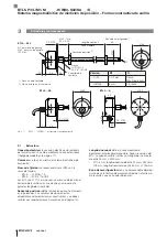
Страница 80: ...to Zona de amortiguaci n1 BTL5 KA _ _ BTL5 K_ _ BTL5 S32 Sensor de posici n2 1 1 Zona no aprovechable 2 No se incluye en el suministro Longitud nominal Zona medible 3 1 Estructura Conexi n el ctrica l...

Страница 81: ...s nica La onda de torsi n que se propaga hacia el extremo del gu aondas se absorbe en la zona de amortiguaci n La onda de torsi n que se propaga hacia el inicio del gu aondas genera una se al el ctric...

Страница 82: ...ico 4 2 Preparaci n del montaje Variante de montaje para alojar el BTL y el sensor de posici n recomendamos un material no imantable Montaje horizontal en caso de montaje horizontal con longitudes nom...

Страница 83: ...l cilindro El material del elemento de deslizamiento se debe adaptar a la carga correspondiente el medio empleado y las temperaturas resultantes Se pueden utilizar por ejemplo Torlon tefl n o bronce F...

Страница 84: ...art Stop 1er flanco 3 PK Rosa Init 4 RD Rojo no utilizado1 5 GN Verde Start Stop 2 flanco Start Stop tri State 2 flanco Tor Start Stop 1er flanco 6 BU Azul GND 7 BN Marr n 20 28 V 8 WH Blanco no utili...

Страница 85: ...del control Campos magn ticos El sistema de medici n de posici n es un sistema magnetostrictivo Preste atenci n a que exista suficiente distancia entre el BTL y el cilindro de alojamiento y campos mag...

Страница 86: ...d del fabricante de la instalaci n o sistema 1 Compruebe que las conexiones est n asentadas firmemente y tengan la polaridad correcta Sustituya las conexiones da adas 2 Conecte el sistema 3 Compruebe...

Страница 87: ...nector atornillado IP67 Cable IP683 2 6 3 Alimentaci n de tensi n externa Tensi n estabilizada5 20 28 V DC Ondulaci n residual 0 5 Vss Consumo de corriente con 24 V DC 90 mA Corriente de pico 3 A Prot...

Страница 88: ...dable Grosor de pared de la varilla Con 8 mm Con 10 2 mm 0 9 mm 2 mm Fijaci n de la carcasa mediante rosca M18 1 5 o 3 4 16UNF BTL5 K_ _ BTL5 KA_ _ Material de cable PUR cULus 20549 80 C 300 V cablead...

Страница 89: ...volumen de suministro de los sensores de posici n BTL P 1013 4R BTL P 1013 4S BTL P 1012 4R incluye Elemento distanciador 8 mm material polioximetileno POM Sensor de posici n BTL5 P 4500 1 electroim...

Страница 90: ...Posibilidad de pedir longitudes de cable distintas p ej BKS S232 PU 05 longitud de cable 5 m Fig 7 5 20 66 Conector BKS S232 PU _ _ BKS S233 PU _ _ Conector acodado recubierto confeccionado M16 8 pol...

Страница 91: ...de varilla fijaci n H rosca de fijaci n m trica M18 1 5 junta t rica di metro de varilla 10 2 mm W rosca inglesa 3 4 16UNF junta t rica di metro de varilla 10 2 mm H8 rosca de fijaci n m trica M18 1 5...

Страница 92: ...pulgada 25 4 mm pulgadas mm 1 25 4 2 50 8 3 76 2 4 101 6 5 127 6 152 4 7 177 8 8 203 2 9 228 6 10 254 Tab 9 2 Tabla de conversi n pulgadas mm 9 Anexo 9 2 Placa de caracter sticas Fig 9 1 Placa de cara...

Страница 93: ......

Страница 94: ...e KY 41042 Phone 859 727 2200 Toll free 1 800 543 8390 Fax 859 727 4823 technicalsupport balluff com CN Service Center China Balluff Shanghai trading Co ltd Room 1006 Pujian Rd 145 Shanghai 200127 P R...

Отзывы: