background image

www.balluff.com

17

english

6.5 

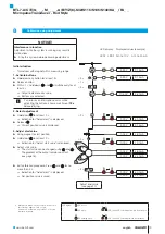
Calibration procedure notes

Prerequisites

–  The calibration device is in place or the programming 

inputs are connected.

–  The transducer is connected to the system controller.

–  Voltage or current values from the transducer can be 

read (using a multimeter or the system controller).

Values for zero and end point

–  Any desired position of the magnet can be used as the 

zero or end point. However, the zero and end points 

may not be reversed.

–  The absolute zero and end points must lie within the 

minimum or maximum limits of what can be output 

(see value table).

–  The distance between the null point and end point 

must be at least 4 mm.

The last set values are always saved, regardless 

of whether the setting was ended using the 

buttons, the programming inputs or 

automatically after 10 min. have expired.

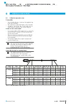
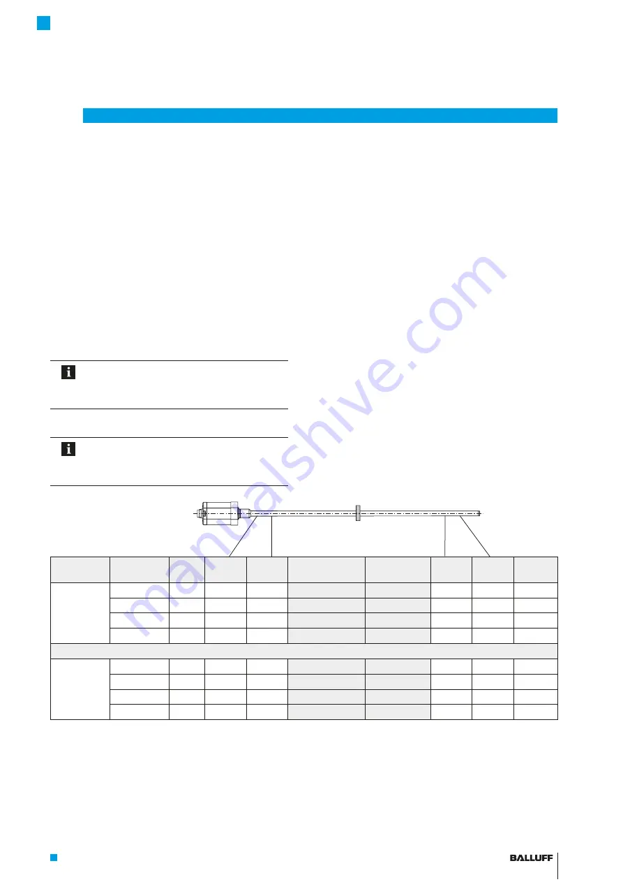
Value table for teach-in and adjustment

The following examples refer to transducers 

with 0 to 10 V or 4 to 20 mA output.

For all other versions, use the values in the 

value table below.


Output 

gradient

Linear 

transducer

Unit

Min. 

value

Null 

value

Identification 

for adjustment

Identification 

for teach-in

End 

value

Max. 

value

Error 

value

Rising

BTL7-A…

V

-

0.5

0

2.0

4.0

+10.0

+10.5

+10.5

BTL7-G…

V

-

10.5

-

10.0

2.0

4.0

+10.0

+10.5

+10.5

BTL7-C…

mA

0

0

6.0

12.0

20.0

20.4

20.4

BTL7-E…

mA

3.6

4.0

6.0

12.0

20.0

20.4

3.6

Falling

BTL7-A…

V

+10.5

+10.0

8.0

6.0

0

-

0.5

-

0.5

BTL7-G…

V

+10.5

+10.0

-

2.0

-

4.0

-

10.0

-

10.5

-

10.5

BTL7-C…

mA

20.4

20.0

14.0

8.0

0

0

20.4

BTL7-E…

mA

20.4

20.0

14.0

8.0

4.0

3.6

3.6

Tab. 6-1:  Value table for teach-in and adjustment

Null point

End point

6


Calibration procedure (continued)

BTL7-A/C/E/G_ _ _-M_ _ _ _-A/B/Y/Z(8)-S32/S115/S135/S140/KA_ _/FA_ _

Micropulse Transducer - Rod Style

Содержание BTL7-A Series

Страница 1: ...Betriebsanleitung deutsch BTL7 A C E G_ _ _ M_ _ _ _ A B Y Z 8 S32 S115 S135 S140 BTL7 A C E G_ _ _ M_ _ _ _ A B Y Z 8 KA_ _ FA_ _...

Страница 2: ...www balluff com...

Страница 3: ...ss 9 4 1 Einbauvarianten 9 4 2 Einbau vorbereiten 9 4 3 Wegaufnehmer einbauen 10 4 3 1 Einbauempfehlung f r Hydraulikzylinder 10 4 4 Elektrischer Anschluss 11 4 4 1 Steckverbinder S32 Kabelanschluss 1...

Страница 4: ...ungsversorgung extern 23 11 4 Ausgang 23 11 5 Eingang 23 11 6 Ma e Gewichte 24 12 Zubeh r 25 12 1 Positionsgeber 25 12 2 Befestigungsmutter 25 12 3 Steckverbinder und Kabel 26 12 3 1 BKS S32 S33M 00 f...

Страница 5: ...folgenden Fachgrundnormen EN 61000 6 1 St rfestigkeit EN 61000 6 2 St rfestigkeit EN 61000 6 3 Emission EN 61000 6 4 Emission und folgende Produktnorm EN 61326 2 3 Emissionspr fungen Funkst rstrahlung...

Страница 6: ...er Betreiber hat die Verantwortung dass die rtlich geltenden Sicherheitsvorschriften eingehalten werden Insbesondere muss der Betreiber Ma nahmen treffen dass bei einem Defekt des Wegmesssystems keine...

Страница 7: ...g des Wegaufneh mers sind St be mit Nennl ngen von 25 mm bis 7620 mm lieferbar 10 2 mm Nennl nge von 25 mm bis 7620 mm 8 mm Nennl nge von 25 mm bis 1016 mm D mpfungszone Messtechnisch nicht nutzbarer...

Страница 8: ...der D mpfungszone absorbiert Die zum Anfang des Wellenleiters laufende Torsionswelle erzeugt in einer Abnehmerspule ein elektrisches Signal Aus der Laufzeit der Welle wird die Position bestimmt Je na...

Страница 9: ...durchmesser bei Einbau in einen Hydraulikzylinder 4 2 Einbau vorbereiten Einbauvariante F r die Aufnahme des Wegaufnehmers und des Positionsgebers empfehlen wir nichtmagnetisier bares Material Waagere...

Страница 10: ...en liegt in der Verantwortung des Zylinderherstellers Der Werkstoff des Gleitelements muss auf den Belastungs fall das eingesetzte Medium und die auftretenden Tempe raturen abgestimmt sein M glich sin...

Страница 11: ...rot La Programmiereingang 5 GN gr n 0 10 V 10 10 V nicht belegt1 8 WH wei Lb Programmiereingang BTL7 _1_ _ BTL7 _5_ _ 6 BU blau GND2 GND2 7 BN braun 20 bis 28 V 10 bis 30 V 1 Nicht belegte Adern k nn...

Страница 12: ...binder S140 S140 Pin Schnittstelle BTL7 A B C J K G H E D F Bild 4 12 Pinbelegung S140 Draufsicht auf Stecker am Wegaufnehmer 10 poliger Rundstecker A_10 G_10 C_00 C_70 E_00 E_70 A 0 V B nicht belegt...

Страница 13: ...Kabelschirm erden mit dem Schutzleiter verbinden Magnetfelder Das Wegmesssystem ist ein magnetostriktives System Auf ausreichenden Abstand des Wegaufnehmers und des Aufnahmezylinders zu starken exter...

Страница 14: ...en oder Systemher stellers beachten 1 Anschl sse auf festen Sitz und richtige Polung pr fen Besch digte Anschl sse tauschen 2 System einschalten 3 Messwerte und einstellbare Parameter pr fen und ggf d...

Страница 15: ...ster 2 Programmiereingang auf 20 bis 28 V BTL7 _1_ _ bzw 10 bis 30 V BTL7 _5_ _ entspricht Taster gedr ckt high aktiv Automatische Deaktivierung Werden ber die Programmiereing nge ca 10 min keine Sign...

Страница 16: ...Bild 6 5 Neuer Endwert vorher nachher Endpunkt Neue Endposition justieren nderung der Steigung der Kennlinie 6 3 3 Online Setting Die detaillierte Vorgehensweise f r das Online Setting ist auf Seite 2...

Страница 17: ...Programmiereing nge oder automatisch nach 10 min beendet wurde Wertetabelle f r Teach in und Justieren Die Darstellung in den nachfolgenden Einstell beispielen beziehen sich auf die Wegaufnehmer mit S...

Страница 18: ...wird angezeigt 4 00 V 12 00 mA loslassen Aktueller Positionswert wird angezeigt 5 39 V 9 15 mA 3 Nullpunkt einstellen Positionsgeber an den neuen Nullpunkt bringen 1 04 V 4 82 mA mindestens 2 s dr cke...

Страница 19: ...ionswert wird angezeigt 5 39 V 9 15 mA 3 Anfangswert justieren Positionsgeber in die Anfangsposition bringen 1 04 V 4 82 mA mindestens 2 s dr cken 2 s 1 Kennung Anfangswert justieren wird angezeigt 0...

Страница 20: ...pr fen Die Einstellungen von Anfangswert und Endwert beeinflussen sich abh ngig von der Messposition gegenseitig Schritte 3 und 4 so oft wiederholen bis die gew nschten Werte exakt einge stellt sind...

Страница 21: ...ei konstant siehe Seite 16 4 84 V 11 74 mA Einstellung beenden 15 s lang keinen Taster dr cken Anfangswert ist gespeichert Taster sind deaktiviert 4 84 V 11 74 mA Nach jedem Einstellvorgang die Verrie...

Страница 22: ...5 39 V 10 80 mA Taster loslassen 1 s Innerhalb 1 s und gleichzeitig dr cken und mindestens 3 s gedr ckt halten 3 s 1 2 Ausgang gibt Errorwert aus 10 50 V 3 60 mA Taster sind aktiviert Tritt ein Fehler...

Страница 23: ...Stecker in verschraub tem Zustand IP 67 Kabel IP 683 2 11 3 Spannungsversorgung extern Spannung stabilisiert4 BTL7 _1_ _ BTL7 _5_ _ 20 bis 28 V DC 10 bis 30 V DC Restwelligkeit 0 5 Vss Stromaufnahme...

Страница 24: ...4 16UNF Anzugsdrehmoment max 100 Nm BTL7 KA_ _ Kabelmaterial PUR cULus 20549 80 C 300 V internal wiring Kabeltemperatur 40 C 90 C Kabeldurchmesser max 7 mm zul ssiger Biegeradius feste Verlegung 35 mm...

Страница 25: ...1013 4R BTL P 1013 4S BTL P 1012 4R enthalten Distanzst ck 8 mm Material Polyoxymethylen POM Positionsgeber BTL5 P 4500 1 Elektromagnet Gewicht ca 90 g Geh use Kunststoff Betriebstemperatur 40 C bis 6...

Страница 26: ...nder gerade umspritzt konfektioniert M16 8 polig Unterschiedliche Kabell ngen bestellbar z B BKS S232 PU 05 Kabell nge 5 m Bild 12 4 20 66 Steckverbinder BKS S232 PU _ _ BKS S233 PU _ _ Steckverbinder...

Страница 27: ...S116 PU_ _ Abgang Pin Farbe 1 YE gelb 2 GY grau 3 PK rosa 4 RD rot 5 GN gr n 6 BU blau 7 BN braun 8 WH wei Tab 12 1 Pinbelegung BKS S115 116 PU _ _ 12 3 4 BKS S135 S136M 00 frei konfektionierbar BKS S...

Страница 28: ...12 Vierkantflansch M12 Kontakteinsatz Stecksystem am Beispiel Einbau des Wegaufnehmers in einen Hydraulikzylinder Baureihe ZA10 Material Vierkantflansch Messing vernickelt BTL7 KA00 2 ZA10 PUR Kabel 0...

Страница 29: ...version Befestigung A metrisches Befestigungsgewinde M18x1 5 Stabdurchmesser 10 2 mm B metrisches Befestigungsgewinde M18x1 5 O Ring Stabdurchmesser 10 2 mm Y Zollgewinde 3 4 16UNF Stabdurchmesser 10...

Страница 30: ...71 10 0 393700787 Tab 14 1 Umrechnungstabelle mm inch 1 inch 25 4 mm inch mm 1 25 4 2 50 8 3 76 2 4 101 6 5 127 6 152 4 7 177 8 8 203 2 9 228 6 10 254 Tab 14 2 Umrechnungstabelle inch mm 14 2 Typensch...

Страница 31: ...ny Balluff GmbH Schurwaldstrasse 9 73765 Neuhausen a d F Phone 49 7158 173 370 Fax 49 7158 173 691 service balluff de US Service Center USA Balluff Inc 8125 Holton Drive Florence KY 41042 Phone 859 72...

Страница 32: ...User s Guide english BTL7 A C E G_ _ _ M_ _ _ _ A B Y Z 8 S32 S115 S135 S140 BTL7 A C E G_ _ _ M_ _ _ _ A B Y Z 8 KA_ _ FA_ _...

Страница 33: ...www balluff com...

Страница 34: ...ion guidelines 9 4 2 Preparing for installation 9 4 3 Installing the transducer 10 4 3 1 Installation recommendation for hydraulic cylinders 10 4 4 Electrical connection 11 4 4 1 Connector type S32 ca...

Страница 35: ...Supply voltage external 23 11 4 Output 23 11 5 Input 23 11 6 Dimensions weights 24 12 Accessories 25 12 1 Magnets 25 12 2 Mounting nut 25 12 3 Connectors and cables 26 12 3 1 BKS S32 S33M 00 freely c...

Страница 36: ...e immunity EN 61000 6 2 noise immunity EN 61000 6 3 emission EN 61000 6 4 emission and the following product standard EN 61326 2 3 Emission tests RF emission EN 55016 2 3 industrial and residential ar...

Страница 37: ...to the work to be done The operator is responsible for ensuring that local safety regulations are observed In particular the operator must take steps to ensure that a defect in the position measuring...

Страница 38: ...onnector see Ordering code on page 29 BTL housing Aluminum housing containing the processing electronics Mounting thread We recommend assembling this transducer on the mounting thread BTL7 A B M18 1 5...

Страница 39: ...ion The component of the torsional wave which arrives at the beginning of the waveguide is converted by a coil into an electrical signal The travel time of the wave is used to calculate the position D...

Страница 40: ...transducer and magnet Horizontal assembly If installing horizontally with nominal lengths 500 mm we recommend tightening the outer rod at the end only possible with 10 2 mm or supporting it Hydraulic...

Страница 41: ...detailed solutions is the responsibility of the cylinder manufacturer The sliding element material must be suitable for the appropriate load case medium used and application temperatures E g Torlon T...

Страница 42: ...TL7 _1_ _ BTL7 _5_ _ 6 BU blue GND2 GND2 7 BN brown 20 to 28 V 10 to 30 V 1 Unassigned leads can be connected to the GND on the controller side but not to the shield 2 Reference potential for supply v...

Страница 43: ...Connector type S140 S140 Pin Interface BTL7 A B C J K G H E D F Fig 4 12 Pin assignment of S140 view of connector pins of transducer 10 pin circular plug 1 Unassigned leads can be connected to the GN...

Страница 44: ...fields The position measuring system is a magnetostrictive system It is important to maintain adequate distance between the transducer cylinder and strong external magnetic fields Cable routing Do no...

Страница 45: ...tem manufacturer 1 Check connections for tightness and correct polarity Replace damaged connections 2 Turn on the system 3 Check measured values and adjustable parameters and readjust the transducer i...

Страница 46: ...2 Programming input at 20 to 28 V BTL7 _1_ _ or 10 to 30 V BTL7 _5_ _ corresponds to button depressed high active Automatic deactivation If no signals are sent over the programming inputs for approx 1...

Страница 47: ...rt value Null point Before After New end value Before After End point 6 3 3 Online setting The detailed procedure for online setting is described on page 21 Setting start and end values while the syst...

Страница 48: ...ttons the programming inputs or automatically after 10 min have expired Value table for teach in and adjustment The following examples refer to transducers with 0 to 10 V or 4 to 20 mA output For all...

Страница 49: ...for Teach in is displayed 4 00 V 12 00 mA Release Current position value is displayed 5 39 V 9 15 mA 3 Set null point Bring magnet to the new null point 1 04 V 4 82 mA Hold down for at least 2 s 2 s...

Страница 50: ...sition value is displayed 5 39 V 9 15 mA 3 Adjust start value Bring magnet to start position 1 04 V 4 82 mA Hold down for at least 2 s 2 s 1 Indication for Adjust start value is displayed 0 00 V 4 00...

Страница 51: ...19 00 mA Check values The settings for the start value and end value have a mutual effect depending on the measuring position Repeat steps 3 and 4 until the desired values are exactly set 5 Exit adjus...

Страница 52: ...ge 16 4 84 V 11 74 mA Exit setting do not press a button for at least 15 s The start value is saved the buttons are deactivated 4 84 V 11 74 mA After each calibration procedure you must wait for the l...

Страница 53: ...3 s 3 s 2 1 5 39 V 10 80 mA Release button 1 s Within 1 s hold down and simultaneously for at least 3 s 3 s 1 2 Output indicates error value 10 50 V 3 60 mA Buttons are activated If an error or an in...

Страница 54: ...0529 Connector when attached IP 67 Cable IP 683 11 3 Supply voltage external Voltage stabilized4 BTL7 _1_ _ BTL7 _5_ _ 20 to 28 V DC 10 to 30 V DC Ripple 0 5 Vss Current draw at 24 V DC 150 mA Inrush...

Страница 55: ...8 1 5 or 3 4 16UNF Tightening torque Max 100 Nm BTL7 KA_ _ Cable material PUR cULus 20549 80 C 300 V internal wiring Cable temperature 40 C to 90 C Cable diameter Max 7 mm Permissible bending radius F...

Страница 56: ...or BTL P 1013 4R BTL P 1013 4S BTL P 1012 4R magnets includes Spacer 8 mm material polyoxymethylene POM BTL5 P 4500 1 magnet solenoid Weight Approx 90 g Housing Plastic Operating temperature 40 C to 6...

Страница 57: ...r molded preassembled M16 8 pin Various cable lengths can be ordered e g BKS S232 PU 05 Cable length 5 m Fig 12 4 20 66 Connector type BKS S232 PU _ _ BKS S233 PU _ _ Angled connector molded preassemb...

Страница 58: ...ype BKS S116 PU_ _ outlet Pin Color 1 YE yellow 2 GY grey 3 PK pink 4 RD red 5 GN green 6 BU blue 7 BN brown 8 WH white Tab 12 1 BKS S115 116 PU _ _ pin assignment 12 3 4 BKS S135 S136M 00 freely conf...

Страница 59: ...12 Square flange M12 contact insert Plug in system based on the example installing the transducer in a hydraulic cylinder Series ZA10 Square flange material Nickel plated brass BTL7 KA00 2 ZA10 PUR ca...

Страница 60: ...M0025 to M1016 A8 B8 Y8 Z8 M0025 to M7620 A B Y Z Rod version fastening A Metric mounting thread M18x1 5 rod diameter 10 2 mm B Metric mounting thread M18x1 5 O ring rod diameter 10 2 mm Y 3 4 16UNF...

Страница 61: ...10 0 393700787 Tab 14 1 Conversion table mm to inches 1 inch 25 4 mm inches mm 1 25 4 2 50 8 3 76 2 4 101 6 5 127 6 152 4 7 177 8 8 203 2 9 228 6 10 254 Tab 14 2 Conversion table inches to mm 14 2 Pa...

Страница 62: ...any Balluff GmbH Schurwaldstrasse 9 73765 Neuhausen a d F Phone 49 7158 173 370 Fax 49 7158 173 691 service balluff de US Service Center USA Balluff Inc 8125 Holton Drive Florence KY 41042 Phone 859 7...

Страница 63: ...Manual de instrucciones espa ol BTL7 A C E G_ _ _ M_ _ _ _ A B Y Z 8 S32 S115 S135 S140 BTL7 A C E G_ _ _ M_ _ _ _ A B Y Z 8 KA_ _ FA_ _...

Страница 64: ...www balluff com...

Страница 65: ...conexi n 9 4 1 Variantes de montaje 9 4 2 Preparaci n del montaje 9 4 3 Montaje del transductor de desplazamiento 10 4 3 1 Recomendaci n de montaje para cilindros hidr ulicos 10 4 4 Conexi n el ctrica...

Страница 66: ...Alimentaci n de tensi n externa 23 11 4 Salida 23 11 5 Entrada 23 11 6 Medidas pesos 24 12 Accesorios 25 12 1 Sensores de posici n 25 12 2 Tuerca de fijaci n 25 12 3 Conectores y cables 26 12 3 1 BKS...

Страница 67: ...inmunidad a las interferencias EN 61000 6 2 inmunidad a las interferencias EN 61000 6 3 emisi n EN 61000 6 4 emisi n y la siguiente norma de producto EN 61326 2 3 Pruebas de emisiones Radiaci n parasi...

Страница 68: ...es responsable de respetar las normas de seguridad locales vigentes En particular el explotador debe adoptar medidas destinadas a evitar peligros para las personas y da os materiales si se produce al...

Страница 69: ...nte un conector v ase el c digo de modelo en la p gina 29 Carcasa del BTL carcasa de aluminio en la que se encuentra el sistema electr nico de evaluaci n Rosca de fijaci n Se recomienda montar estos t...

Страница 70: ...torsi n que se propaga hacia el inicio del gu aondas genera una se al el ctrica en una bobina captadora La posici n se determina a partir del tiempo de propagaci n de la onda Seg n la versi n sta se e...

Страница 71: ...taje horizontal con longitudes nominales 500 mm recomendamos atornillar s lo posible con 10 2 mm o apoyar el tubo de protecci n en el extremo Cilindro hidr ulico en el montaje en un cilindro hidr u li...

Страница 72: ...l cilindro El material del elemento de deslizamiento se debe adaptar a la carga correspondiente el medio empleado y las temperaturas resultantes Se pueden utilizar por ejemplo Torlon tefl n o bronce F...

Страница 73: ...TL7 _1_ _ BTL7 _5_ _ 6 BU azul GND2 GND2 7 BN marr n de 20 a 28 V de 10 a 30 V 1 Los conductores no utilizados se pueden conectar en el lado del control con GND pero no con el blindaje 2 Potencial de...

Страница 74: ...S140 S140 Pin Interfaz BTL7 A B C J K G H E D F Asignaci n de pines S140 vista desde arriba del conector en el transductor de desplazamiento conector cil ndrico de 10 polos A_10 G_10 C_00 C_70 E_00 E...

Страница 75: ...el conductor protector Campos magn ticos El sistema de medici n de desplazamiento es un sistema magnetostrictivo Preste atenci n a que exista suficiente distancia entre el transductor de desplazamient...

Страница 76: ...sentadas firmemente y tengan la polaridad correcta Sustituya las conexiones da adas 2 Conecte el sistema 3 Compruebe los valores de medici n y los par metros ajustables y en caso necesario reajuste el...

Страница 77: ...7 _1_ _ o bien en 10 hasta 30 V BTL7 _5_ _ corresponde a pulsador accionado alto activo Desactivaci n autom tica Si durante aprox 10 minutos no se transmiten se ales a trav s de las entradas de progra...

Страница 78: ...inicial Punto cero antes despu s Nuevo valor final antes despu s Punto final 6 3 3 Configuraci n online El procedimiento detallado para la configuraci n online est descrito en la p gina 21 Ajuste de l...

Страница 79: ...entradas de programaci n o autom ticamente al cabo de 10 minutos Tabla de valores para aprendizaje y ajuste La representaci n de los siguientes ejemplos de ajuste se refiere a los transductores de des...

Страница 80: ...s 2 s 2 s Se muestra la indicaci n para Aprendizaje 4 00 V 12 00 mA Suelte Se muestra el valor de posici n actual 5 39 V 9 15 mA 3 Ajustar el punto cero Lleve el sensor de posici n al nuevo punto cero...

Страница 81: ...l valor de posici n actual 5 39 V 9 15 mA 3 Ajustar el valor inicial Lleve el sensor de posici n a la posici n inicial 1 04 V 4 82 mA Accione durante al menos 2 s 2 s 1 Se muestra la identificaci n pa...

Страница 82: ...nicial y del valor final se influyen mutuamente en funci n de la posici n de medici n Repita los pasos 3 y 4 tantas veces como sea necesario hasta que haya ajustado exactamente los valores deseados 5...

Страница 83: ...a p gina 16 4 84 V 11 74 mA Finalice el ajuste no accione ning n pulsador durante 15 s El valor inicial se ha guardado los pulsadores est n desactivados 4 84 V 11 74 mA Despu s de cada proceso de ajus...

Страница 84: ...e 1 s accione y al mismo tiempo y mant ngalos accionados durante 3 s como m nimo 3 s 1 2 La salida emite un valor de error 10 50 V 3 60 mA Los pulsadores est n activados Si se produce un error o una i...

Страница 85: ...imentaci n de tensi n externa Tensi n estabilizada4 BTL7 _1_ _ BTL7 _5_ _ De 20 a 28 V DC De 10 a 30 V DC Ondulaci n residual 0 5 Vss Consumo de corriente con 24 V DC 150 mA Corriente de pico 500 mA 1...

Страница 86: ...16UNF Par de apriete M x 100 Nm BTL7 KA_ _ Material de cable PUR cULus 20549 80 C 300 V cableado interno Temperatura del cable 40 C 90 C Di metro del cable M x 7 mm Radio de flexi n admisible Tendido...

Страница 87: ...013 4S BTL P 1012 4R incluye Elemento distanciador 8 mm material polioximetileno POM Sensor de posici n BTL5 P 4500 1 electroim n Peso Aprox 90 g Carcasa Material sint tico Temperatura de servicio De...

Страница 88: ...osibilidad de pedir longitudes de cables distintas p ej BKS S232 PU 05 longitud de cable 5 m Fig 12 4 20 66 Conector BKS S232 PU _ _ BKS S233 PU _ _ Conector acodado recubierto por extrusi n confeccio...

Страница 89: ...salida Pin Color 1 YE amarillo 2 GY gris 3 PK rosa 4 RD rojo 5 GN verde 6 BU azul 7 BN marr n 8 WH blanco Tab 12 1 Asignaci n de pines BKS S115 116 PU _ _ 12 3 4 BKS S135 S136M 00 libremente confeccio...

Страница 90: ...2 Flangia quadrata Portacontatti M12 Sistema enchufable en el ejemplo del montaje del trans ductor de desplazamiento en un cilindro hidr ulico Serie ZA10 Material de la brida cuadrada lat n galvanizad...

Страница 91: ...fijaci n A rosca de fijaci n m trica M18x1 5 di metro de varilla 10 2 mm B rosca de fijaci n m trica M18x1 5 junta t rica di metro de varilla 10 2 mm Y rosca inglesa 3 4 16UNF di metro de varilla 10...

Страница 92: ...conversi n mm pulgadas 1 pulgada 25 4 mm pulga das mm 1 25 4 2 50 8 3 76 2 4 101 6 5 127 6 152 4 7 177 8 8 203 2 9 228 6 10 254 Tab 14 2 Tabla de conversi n pulgadas mm 14 2 Placa de caracter sticas...

Страница 93: ...enter Germany Balluff GmbH Schurwaldstrasse 9 73765 Neuhausen a d F Phone 49 7158 173 370 Fax 49 7158 173 691 service balluff de US Service Center USA Balluff Inc 8125 Holton Drive Florence KY 41042 P...

Страница 94: ...Notice d utilisation fran ais BTL7 A C E G_ _ _ M_ _ _ _ A B Y Z 8 S32 S115 S135 S140 BTL7 A C E G_ _ _ M_ _ _ _ A B Y Z 8 KA_ _ FA_ _...

Страница 95: ...www balluff com...

Страница 96: ...riantes de montage 9 4 2 Pr paration du montage 9 4 3 Montage du capteur de d placement 10 4 3 1 Recommandation de montage pour v rin hydraulique 10 4 4 Raccordement lectrique 11 4 4 1 Connecteur S32...

Страница 97: ...tes 23 11 3 Alimentation lectrique externe 23 11 4 Sorties 23 11 5 Entr es 23 11 6 Dimensions poids 24 12 Accessoires 25 12 1 Capteurs de position 25 12 2 Ecrou de fixation 25 12 3 Connecteurs et c bl...

Страница 98: ...istance au brouillage EN 61000 6 2 r sistance au brouillage EN 61000 6 3 mission EN 61000 6 4 mission Et a la norme de produits suivante EN 61326 2 3 Contr les de l mission Rayonnement parasite EN 550...

Страница 99: ...rit ad quates Il est de la responsabilit de l exploitant de veiller ce que les dispositions locales concernant la s curit soient respect es L exploitant doit en particulier prendre les mesures n cessa...

Страница 100: ...age 29 Bo tier BTL bo tier en aluminium dans lequel se trouve le syst me de mesure lectronique Filet de fixation Le cas ch ant nous recommandons le montage des capteurs de d placement suivants BTL7 A...

Страница 101: ...t L onde de torsion au d but du guide d ondes g n re un signal lectrique dans une bobine r ceptrice La position est d termin e d apr s la dur e de propagation de l onde Selon le mod le elle sera carac...

Страница 102: ...ables Montage horizontal en cas de montage horizontal avec des longueurs nominales 500 mm nous recommandons de visser uniquement possible pour 10 2 mm ou de supporter l extr mit du tube de protection...

Страница 103: ...xtr mit de la tige Le dimensionnement des solutions d taill es incombe au fabricant du v rin Le mat riau de cet l ment coulissant doit tre adapt aux types de charge produits et temp ratures utilis s S...

Страница 104: ...n BTL7 _1_ _ BTL7 _5_ _ 6 BU bleu GND2 GND2 7 BN marron 20 28 V 10 30 V 1 Les conducteurs non utilis s peuvent tre reli s cot commande la masse GND mais pas au blindage 2 Potentiel de r f rence pour t...

Страница 105: ...eur S140 S140 Broche Interface BTL7 A B C J K G H E D F Fig 4 12 Brochage du connecteur S140 vue de dessus sur le connecteur du capteur de d placement connecteur rond 10 p les 1 Les conducteurs non ut...

Страница 106: ...ues Le syst me de mesure de d placement est un syst me magn tostrictif Veiller ce que le capteur de d placement et le v rin de r ception se trouvent une distance suffisante de champs magn tiques exter...

Страница 107: ...du fabricant doivent tre respect es 1 V rifier la fixation et la polarit des raccordements Remplacer les raccordements endommag s 2 Mettre en marche le syst me 3 V rifier les valeurs mesur es et les...

Страница 108: ...ou 10 30 V BTL7 _5_ _ correspond l tat bouton appuy active l tat haut D sactivation automatique Si aucun signal n est transmis par le biais des entr es de programmation pendant env 10 minutes le mode...

Страница 109: ...ourbe Nouvelle valeur initiale Point z ro avant apr s Nouvelle valeur finale avant apr s Fin de plage 6 3 3 R glage en ligne Online La proc dure d taill e pour le r glage en ligne Online est d crite l...

Страница 110: ...e a t quitt e par l interm diaire des boutons poussoirs des entr es de programmation ou automatiquement apr s 10 minutes Tableau des valeurs pour l apprentissage et l ajustage Les exemples de r glage...

Страница 111: ...ndant au moins 2 s 2 s La valeur pour Apprentissage est affich e 4 00 V 12 00 mA Rel cher La valeur de position actuelle est affich e 5 39 V 9 15 mA 3 R gler le point z ro Amener le capteur de positio...

Страница 112: ...ich e 2 00 V 6 00 mA Rel cher La valeur de position actuelle est affich e 5 39 V 9 15 mA 3 Ajuster la valeur initiale Amener le capteur de position en position initiale 1 04 V 4 82 mA Appuyer sur pend...

Страница 113: ...ale et de la valeur finale s influencent mutuellement en fonction de la position de mesure R p ter les tapes 3 et 4 jusqu ce que les valeurs souhait es soient r gl es avec pr cision 5 Terminer l ajust...

Страница 114: ...16 4 84 V 11 74 mA Quitter le r glage n appuyer sur aucun bouton poussoir pendant 15 s La valeur initiale est enregistr e les boutons poussoirs sont d sactiv s 4 84 V 11 74 mA Apr s chaque proc dure d...

Страница 115: ...s poussoir 1 s En l espace d 1 s appuyer simultan ment sur et puis maintenir les boutons enfonc s pendant au moins 3 s 3 s 1 2 La sortie d livre une valeur d erreur 10 50 V 3 60 mA Les boutons poussoi...

Страница 116: ...tation lectrique externe Tension stabilis e4 BTL7 _1_ _ BTL7 _5_ _ 20 28 V CC 10 30 V CC Ondulation r siduelle 0 5 Vss Consommation de courant 24 V CC 150 mA Courant de cr te au d marrage 500 mA 10 ms...

Страница 117: ...UNF Couple de serrage Max 100 Nm BTL7 KA_ _ Mat riau du c ble PUR cULus 20549 80 C 300 V c blage interne Temp rature de c ble 40 C 90 C Diam tre de c ble Max 7 mm Rayon de courbure autoris Pose fixe 3...

Страница 118: ...de position BTL P 1013 4R BTL P 1013 4S BTL P 1012 4R Bague d cartement 8 mm polyoxym thyl ne POM Capteur de position BTL5 P 4500 1 lectro aimant Poids Env 90 g Bo tier Plastique Temp rature de servic...

Страница 119: ...Diff rentes longueurs de c ble disponibles p ex BKS S232 PU 05 longueur de c ble 5 m Fig 12 4 20 66 Connecteur BKS S232 PU _ _ BKS S233 PU _ _ Connecteur coud boudin confectionn M16 8 p les Diff rente...

Страница 120: ...onnecteur BKS S116 PU_ _ sortie Broche Couleur 1 YE jaune 2 GY gris 3 PK rose 4 RD rouge 5 GN vert 6 BU bleu 7 BN marron 8 WH blanc Tab 12 1 Affectation des broches du BKS S115 116 PU _ _ 12 3 4 BKS S...

Страница 121: ...t riel livr Fig 12 12 Bride carr e Connecteur d insertion M12 Syst me de connecteurs l exemple du montage du capteur de d placement dans un v rin hydraulique S rie ZA10 Mat riau de la bride carr e bra...

Страница 122: ...A Filetage de fixation m trique M18x1 5 diam tre de tige 10 2 mm B Filetage de fixation m trique M18x1 5 joint torique diam tre de tige 10 2 mm Y Filetage au pouce 3 4 16UNF diam tre de tige 10 2 mm...

Страница 123: ...00787 Tab 14 1 Conversion mm pouce 1 pouce 25 4 mm pouce mm 1 25 4 2 50 8 3 76 2 4 101 6 5 127 6 152 4 7 177 8 8 203 2 9 228 6 10 254 Tab 14 2 Conversion pouce mm 14 2 Plaque signal tique 2 1 3 3 1 Sy...

Страница 124: ...ermany Balluff GmbH Schurwaldstrasse 9 73765 Neuhausen a d F Phone 49 7158 173 370 Fax 49 7158 173 691 service balluff de US Service Center USA Balluff Inc 8125 Holton Drive Florence KY 41042 Phone 85...

Страница 125: ...BTL7 A C E G_ _ _ M_ _ _ _ A B Y Z 8 S32 S115 S135 S140 BTL7 A C E G_ _ _ M_ _ _ _ A B Y Z 8 KA_ _ FA_ _ Manuale d uso italiano...

Страница 126: ...www balluff com...

Страница 127: ...9 4 2 Preparazione del montaggio 9 4 3 Montaggio del trasduttore di posizione 10 4 3 1 Suggerimento di montaggio per cilindro idraulico 10 4 4 Collegamento elettrico 11 4 4 1 Connettore S32 collegamen...

Страница 128: ...e esterna 23 11 4 Uscita 23 11 5 Ingresso 23 11 6 Dimensioni pesi 24 12 Accessori 25 12 1 Datori di posizione 25 12 2 Dado di fissaggio 25 12 3 Connettori e cavi 26 12 3 1 BKS S32 S33M 00 confezionabi...

Страница 129: ...ti norme fondamentali del settore EN 61000 6 1 immunit alle interferenze EN 61000 6 2 immunit alle interferenze EN 61000 6 3 emissioni EN 61000 6 4 emissioni e della seguente norma di prodotto EN 6132...

Страница 130: ...te Il gestore ha la responsabilit di far rispettare le norme di sicurezza vigenti localmente In particolare il gestore deve adottare provvedimenti tali da poter escludere qualsiasi rischio per persone...

Страница 131: ...i di identificazione a pagina 29 Corpo BTL corpo in alluminio nel quale si trovano i dispositivi elettronici di analisi Filettatura di fissaggio si raccomanda di montare il trasduttore di posizione su...

Страница 132: ...one dell onda torsionale verso l estremit della guida d onda genera un segnale elettrico in una bobina di rilevamento La posizione viene determinata dalla durata di propagazione dell onda A seconda de...

Страница 133: ...con lunghezze nominali 500 mm si consiglia di avvitare possibile solo con 10 2 mm o sostenere il tubo di protezione all estremit Cilindro idraulico per il montaggio in un cilindro idraulico deve esser...

Страница 134: ...e soluzioni dettagliate responsabilit del produttore di cilindri Il materiale dell elemento scorrevole deve essere adattato al caso di carico al mezzo utilizzato e alle temperature ricorrenti Sono pos...

Страница 135: ...zione BTL7 _1_ _ BTL7 _5_ _ 6 BU blu GND2 GND2 7 BN marrone da 20 a 28 V da 10 a 30 V 1 I fili non utilizzati possono essere collegati con GND lato controllo ma non con la schermatura 2 Potenziale di...

Страница 136: ...Interfaccia BTL7 A B C J K G H E D F Fig 4 12 Piedinatura S140 vista in pianta del connettore sul trasduttore di posizi one connettore circolare a 10 poli 1 I fili non utilizzati possono essere colle...

Страница 137: ...e di terra la schermatura del cavo lato comando Campi magnetici Il sistema di misura della corsa un sistema magnetostrittivo Mantenere una distanza sufficiente del trasduttore di posizione e del cilin...

Страница 138: ...e i collegamenti siano fissati saldamente e che la loro polarit sia corretta Sostituire i collegamenti danneggiati 2 Attivare il sistema 3 Controllare i valori misurati e i parametri regolabili ed rei...

Страница 139: ...ne da 20 a 28 V BTL7 _1_ _ o da 10 a 30 V BTL7 _5_ _ corrisponde ad un tasto premuto high attivo Disattivazione automatica Se mediante gli ingressi di programmazione non vengono trasmessi segnali per...

Страница 140: ...curva caratteristica Nuovo valore iniziale Punto zero precedente successivo Nuovo valore finale precedente successivo Punto finale 6 3 3 Online Setting La procedura dettagliata di Online Setting desc...

Страница 141: ...sti con gli ingressi di programmazione oppure automaticamente dopo 10 min di inattivit Tabella dei valori per Teach in e Calibrazione Gli schemi dei seguenti esempi di regolazione sono riferiti ai tra...

Страница 142: ...o il riferimento per Teach in 4 00 V 12 00 mA Rilasciare Verr visualizzato il valore di posizione corrente 5 39 V 9 15 mA 3 Regolazione del punto zero 1 04 V 4 82 mA Portare il datore di posizione sul...

Страница 143: ...di posizione corrente 5 39 V 9 15 mA 3 Calibrazione del valore iniziale Portare il datore di posizione sulla posizione iniziale 1 04 V 4 82 mA Premere per almeno 2 s 2 s 1 Verr visualizzato il riferim...

Страница 144: ...ato 9 00 V 19 00 mA Controllo dei valori Le regolazioni del valore iniziale e finale esercitano un influsso reciproco in base alla posizione di misura Ripetere i passaggi 3 e 4 sino ad impostare esatt...

Страница 145: ...84 V 11 74 mA Terminare la procedura di impostazione non premere nessun tasto per 15 s Il valore iniziale stato salvato i tasti sono inattivi 4 84 V 11 74 mA Dopo la procedura attendere il tempo di bl...

Страница 146: ...no 3 s 3 s 2 1 5 39 V 10 80 mA Rilasciare il tasto 1 s Entro 1 s premere simultaneamente e mantenendoli premuti per almeno 3 s 3 s 1 2 L uscita emette un valore di errore 10 50 V 3 60 mA I tasti sono...

Страница 147: ...IP 683 11 3 Tensione di alimentazione esterna Tensione stabilizzata4 BTL7 _1_ _ BTL7 _5_ _ da 20 a 28 V DC da 10 a 30 V DC Ondulazione residua 0 5 Vss Corrente assorbita con 24 V DC 150 mA Corrente m...

Страница 148: ...3 4 16UNF Coppia di serraggio max 100 Nm BTL7 KA_ _ Materiale cavo PUR cULus 20549 80 C 300 V cablaggio interno Temperatura cavo 40 C 90 C Diametro del cavo max 7 mm Raggio di curvatura consentito Po...

Страница 149: ...TL P 1013 4R BTL P 1013 4S BTL P 1012 4R Distanziale 8 mm materiale poliossimetilene POM Datore di posizione BTL5 P 4500 1 elettromagnete Peso ca 90 g Corpo materiale plastico Temperatura di esercizio...

Страница 150: ...ritto incorporato confezionato M16 8 poli possibile ordinare diverse lunghezze del cavo p es BKS S232 PU 05 lunghezza cavo 5 m Fig 12 4 20 66 Connettore BKS S232 PU _ _ BKS S233 PU _ _ Connettore ad a...

Страница 151: ...1 YE giallo 2 GY grigio 3 PK rosa 4 RD rosso 5 GN verde 6 BU blu 7 BN marrone 8 WH bianco Tab 12 1 Piedinatura Pin BKS S115 116 PU _ _ 12 3 4 BKS S135 S136M 00 confezionabile liberamente BKS S135M 00...

Страница 152: ...a Fig 12 12 Flangia quadrata Portacontatti M12 Esempio di sistema ad innesto in un montaggio del trasduttore di posizione in un cilindro idraulico Serie ZA10 Materiale flangia quadra ottone zincato BT...

Страница 153: ...Versione a barra fissaggio A filettatura di fissaggio metrica M18x1 5 diametro barra 10 2 mm B filettatura di fissaggio metrica M18x1 5 O ring diametro barra 10 2 mm Y filettatura in pollici 3 4 16UNF...

Страница 154: ...abella di conversione mm pollici 1 pollice 25 4 mm pollice mm 1 25 4 2 50 8 3 76 2 4 101 6 5 127 6 152 4 7 177 8 8 203 2 9 228 6 10 254 Tab 14 2 Tabella di conversione pollici mm 14 2 Targhetta identi...

Страница 155: ...ter Germany Balluff GmbH Schurwaldstrasse 9 73765 Neuhausen a d F Phone 49 7158 173 370 Fax 49 7158 173 691 service balluff de US Service Center USA Balluff Inc 8125 Holton Drive Florence KY 41042 Pho...

Отзывы: