background image

4

deutsch

BTL7-A/C/E/G5 _ _ -M _ _ _ _ -K(8)-NEX-SR32/K _ _

Micropulse Wegaufnehmer - Bauform Stab

Zündschutzart

„ec“ und „tb“

10 

Technische Daten 

21

10.1  Genauigkeit 21
10.2  Umgebungsbedingungen 21
10.3  Spannungsversorgung (extern) 

21

10.4  Ausgang 21
10.5  Eingang 21
10.6  Maße, Gewichte 

22

11 

Zubehör 23

11.1  Positionsgeber 23
11.2  Steckverbinder und Kabel 

24

11.3  Einstellbox 24

12 

Typenschlüssel 25

13 

Anhang 26

13.1  Umrechnung Längeneinheiten 

26

13.2  Typenschild 26

Содержание BTL7-A M Series

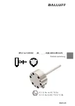
Страница 1: ... M_ _ _ _ K 8 NEX SR32 K_ _ II 3G Ex ec IIC T4 Gc II 2D Ex tb IIIC T135 C Db deutsch Betriebsanleitung english User s Guide français Notice d utilisation italiano Manuale d uso español Manual de instrucciones 中文 使用说明书 ...

Страница 2: ...www balluff com ...

Страница 3: ...Betriebsanleitung deutsch BTL7 A C E G5_ _ M_ _ _ _ K 8 NEX SR32 K_ _ II 3 G Ex ec IIC T4 Gc II 2 D Ex tb IIIC T135 C Db ...

Страница 4: ...www balluff com ...

Страница 5: ... des Betreibers 7 2 5 Montage Installation und Einrichten 7 2 6 Steckverbinder und Positionsgeber 8 2 7 Wartung Prüfung und Reparatur 8 3 Aufbau und Funktion 9 3 1 Aufbau 9 3 2 Funktion 9 4 Einbau und Anschluss 10 4 1 Einbauvarianten 10 4 2 Einbau vorbereiten 10 4 3 Wegaufnehmer einbauen 11 4 3 1 Einbauempfehlung für Hydraulikzylinder 11 4 4 Elektrischer Anschluss 12 4 4 1 Steckverbinder SR32 Kabe...

Страница 6: ...he Daten 21 10 1 Genauigkeit 21 10 2 Umgebungsbedingungen 21 10 3 Spannungsversorgung extern 21 10 4 Ausgang 21 10 5 Eingang 21 10 6 Maße Gewichte 22 11 Zubehör 23 11 1 Positionsgeber 23 11 2 Steckverbinder und Kabel 24 11 3 Einstellbox 24 12 Typenschlüssel 25 13 Anhang 26 13 1 Umrechnung Längeneinheiten 26 13 2 Typenschild 26 ...

Страница 7: ...triebsanleitung Falls die Übersetzun gen inhaltlich nicht eindeutig sind oder Widersprüche auftreten gelten die Angaben der Originalbetriebsanlei tung Sollte eine Betriebsanleitung in der Sprache des Verwen dungslandes fehlen darf der Wegaufnehmer nicht in Betrieb genommen werden Nehmen Sie in diesem Fall Kontakt mit Balluff auf 1 5 Verwendete Symbole und Konventionen Einzelne Handlungsanweisungen...

Страница 8: ...vorrufen können 2 3 Zulassungen Normen und Konformität Mit dem CE Zeichen bestätigen wir dass unsere Produkte den Anforderungen der aktuellen EMV sowie ATEX Richtlinie entsprechen Die Übereinstimmung wird durch die beiliegende Hersteller Konfor mitätserklärung bescheinigt Der Wegaufnehmer erfüllt die Anforderungen der folgenden Produktnorm EN 61326 2 3 Störfestigkeit und Emission Emissionsprüfunge...

Страница 9: ...n Stäuben als auch mit brennbaren Flusen Die Temperaturangabe T135 C kennzeichnet dass die äußere Oberflächentemperatur des Wegaufnehmers bei allen Bedingungen der Gerätekategorie unter 135 C liegt Mit IP6x wird die Staubdichtigkeit des Gehäuses bestätigt 2 4 2 Besondere Bedingungen Symbol X Das Symbol X kennzeichnet besondere Bedingungen die für die sichere Anwendung zu beachten sind Der zulässig...

Страница 10: ...r und Positionsgeber sind im Kapitel 11 Zubehör aufgeführt Für die Wegaufnehmer mit Steckeranschluss sind nur folgende Steckverbinder mit werksseitig konfektioniertem Kabel geprüft und freigegeben BKS S 32M _ _ BKS S 33M _ _ Als Positionsgeber sind nur die Ausführungen aus Kapi tel 11 Zubehör freigegeben Bei Verwendung anderer Anschlussstecker Kabel oder Positionsgeber muss die Eignung entsprechen...

Страница 11: ...00 mm Ø 8 mm Nennlänge von 25 mm bis 1016 mm Dämpfungszone Messtechnisch nicht nutzbarer Bereich am Stabende der überfahren werden darf 3 2 Funktion Im Micropulse Wegaufnehmer befindet sich der Wellenlei ter geschützt durch ein Edelstahlrohr Entlang des Wellen leiters wird ein Positionsgeber bewegt Dieser Positionsge ber ist mit dem Anlagenbauteil verbunden dessen Position bestimmt werden soll Der...

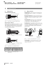
Страница 12: ...i Einbau in einen Hydraulikzylinder 4 2 Einbau vorbereiten Einbauvariante Für die Aufnahme des Wegaufnehmers und des Positionsgebers empfehlen wir nichtmagnetisier bares Material Waagerechte Montage Bei waagerechter Montage mit Nennlängen 500 mm ist der Stab abzustützen und gege benenfalls am Ende anzuschrauben nur bei Ø 10 2 mm möglich Hydraulikzylinder Bei Einbau in einen Hydraulikzylinder ist d...

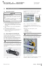
Страница 13: ...ortung des Zylinderherstellers Der Werkstoff des Gleitelements muss auf den Belastungs fall das eingesetzte Medium und die auftretenden Tempe raturen abgestimmt sein Möglich sind z B Torlon Teflon oder Bronze Bild 4 4 Gleitelement Positionsgeber Beispiel 1 Wegaufnehmer wird mit Gleitelement einge baut Das Gleitelement kann aufgeschraubt oder aufgeklebt werden Schraube gegen Lösen oder Verlieren si...

Страница 14: ...ng BTL7 SR32 K_ _ 4 5 Schirmung und Kabelverlegung Definierte Erdung Wegaufnehmer und Schaltschrank müssen auf dem gleichen Erdungspotenzial liegen Schirmung Zur Gewährleistung der elektromagnetischen Verträglich keit EMV sind folgende Hinweise zu beachten Wegaufnehmer und Steuerung mit einem geschirmten Kabel verbinden Schirmung Geflecht aus Kupfer Einzeldrähten Bede ckung mindestens 85 Steckerau...

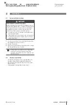
Страница 15: ...s Anlagen oder Systemher stellers beachten 1 Anschlüsse auf festen Sitz und richtige Polung prüfen Beschädigte Anschlüsse tauschen 2 System einschalten 3 Messwerte und einstellbare Parameter prüfen und ggf den Wegaufnehmer neu einstellen Insbesondere nach dem Austausch des Weg aufnehmers oder der Reparatur durch den Hersteller die korrekten Werte im Nullpunkt und Endpunkt prüfen 5 2 Hinweise zum B...

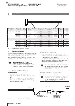
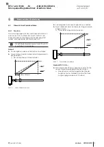
Страница 16: ...n Programmiereingänge sind angeschlossen Wegaufnehmer ist mit der Anlagensteuerung verbun den Spannungs oder Stromwerte des Wegaufnehmers können gelesen werden mittels Multimeter Anlagen steuerung oder Einstellbox Bild 6 1 Anschluss der Einstellbox BTL7 A CB02 S 6 Einstellverfahren Werte für Null und Endpunkt Jede beliebige Position des Positionsgebers kann Null oder Endpunkt sein Null und Endpunk...

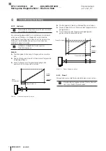
Страница 17: ...elle Endpunkt bleibt erhalten Neuer Nullpunkt vorher nachher Bild 6 2 Neuen Nullpunkt einlesen 6 Einstellverfahren Fortsetzung Positionsgeber in die neue Endposition verschieben Neuen Endpunkt durch Aktivieren der Programmierein gänge einlesen Der aktuelle Nullpunkt bleibt erhalten Neuer Endpunkt vorher nachher Bild 6 3 Neuen Endpunkt einlesen Nur bei BTL7 C E Die Kennlinie des Stromausgangs kann ...

Страница 18: ...en der Programmie reingänge einlesen Durch Aktivieren der Programmiereingänge den gewünschten Anfangswert einstellen Neuer Nullpunkt vorher nachher Bild 6 4 Neuen Anfangswert justieren Positionsgeber in die neue Endposition verschieben Neuen Endpunkt durch Aktivieren der Programmierein gänge einlesen Durch Aktivieren der Programmiereingänge den gewünschten Endwert einstellen Neuer Endpunkt vorher ...

Страница 19: ...t 0 00 V 4 00 mA Endpunkt einstellen Positionsgeber an den neuen Endpunkt bringen 9 89 V 19 13 mA b mindestens 2 s aktivieren 2 s b Der neue Endpunkt ist eingestellt 10 00 V 20 00 mA Kennlinie invertieren nur bei BTL7 C E a und b gleichzeitig mindestens 4 s aktivieren 4 s a b 3 60 mA Errorwert wird angezeigt Nach Loslassen ist die Kennlinie des Ausgangs invertiert 14 85 mA Teach in beenden a und b...

Страница 20: ...en 1 04 V 4 82 mA a mindestens 2 s aktivieren 2 s a Der neue Anfangspunkt ist mit zuletzt gültigem Anfangswert eingestellt 0 00 V 4 00 mA Anfangswert justieren Über a und b kann der Anfangswert verändert werden Die Steigung der Kennlinie ändert sich siehe Seite 16 0 00 V 4 00 mA 0 90 V 7 20 mA Einstellvorgang beenden a und b gleichzeitig kurz 1 s aktivieren 1 s a b 2 00 V 6 00 mA Eingestellter Pos...

Страница 21: ...rt sich siehe Seite 16 10 00 V 20 00 mA 8 00 V 16 80 mA Einstellvorgang beenden a und b gleichzeitig kurz 1 s aktivieren Eingestellter Positionswert wird gespeichert 1 s a b 2 00 V 6 00 mA 8 00 V 16 80 mA Justieren beenden a und b gleichzeitig kurz 1 s aktivieren 1 s a b 10 50 V 3 60 mA Nach Loslassen wird der aktuelle Positionswert angezeigt 7 63 V 18 56 mA Die einzelnen Schritte der Einstellunge...

Страница 22: ...0 10 V bei 4 20 mA 5 39 V 9 15 mA Reset aktivieren a und b gleichzeitig mindestens 4 s aktivieren 4 s a b 10 50 V 3 60 mA Reset a und b gleichzeitig mindestens 4 s aktivieren 4 s a b 0 00 V 4 00 mA Nach Aktivierung Alle Werte sind zurückgesetzt 9 89 V 19 13 mA Aktueller Positionswert wird angezeigt Reset ist deaktiviert Reset abbrechen Das Rücksetzen kann nach dem Schritt Reset aktivieren ohne Änd...

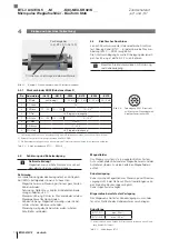
Страница 23: ... 2 272 3 150 g 6 ms 150 g 2 ms Vibration nach EN 60068 2 62 3 20 g 10 2000 Hz Schutzart nach IEC 60529 Stecker SR32 in verschraubtem Zustand IP67 Kabel K_ _ IP682 10 3 Spannungsversorgung extern Spannung stabilisiert BTL7 _5_ _ 10 30 V DC Restwelligkeit 0 5 Vss Stromaufnahme bei 24 V DC 120 mA Einschaltspitzenstrom 500 mA Verpolungssicher4 bis 36 V Überspannungsschutz bis 36 V Spannungsfestigkeit ...

Страница 24: ... Flanschmaterial Edelstahl Stabmaterial Edelstahl Wandstärke Stab bei Ø 8 mm 0 9 mm bei Ø 10 2 mm 2 mm Gehäusebefestigung Flansch mit 6 Bohrungen BTL7 K_ _ Kabelmaterial PUR Kabeldurchmesser max 7 mm zulässiger Biegeradius feste Verlegung 35 mm 10 Technische Daten Fortsetzung BTL7 A C E G5_ _ M_ _ _ _ K 8 NEX SR32 K_ _ Micropulse Wegaufnehmer Bauform Stab Zündschutzart ec und tb ...

Страница 25: ...012 4R BTL P 1014 2R Gewicht 15 g Gehäuse Aluminium Im Lieferumfang der Positionsgeber BTL P 1013 4R BTL P 1013 4S BTL P 1012 4R enthalten Distanzstück 8 mm Material Polyoxymethylen POM BTL P 1028 15R Sonderzubehör für Applikationen mit Stützrohranwendung Gewicht ca 68 g Gehäuse Aluminium Bild 11 2 Ø 4 3 120 Ø 28 Ø 54 Ø 65 8 Sonderzubehör BTL P 1028 15R 11 Zubehör BTL7 A C E G5_ _ M_ _ _ _ K 8 NEX...

Страница 26: ... 5 m Bild 11 4 Ø 18 31 37 2 Ø 20 54 Ø max 7 Steckverbinder BKS S 33M _ _ Bild 11 5 Steckverbinder BKS S 33M _ _ Abgang Pin Farbe 1 YE gelb 2 GY grau 3 PK rosa 4 RD rot 5 GN grün 6 BU blau 7 BN braun 8 WH weiß Tab 11 1 Pinbelegung BKS S 32 33M _ _ 11 3 Einstellbox BTL7 A CB02 S32 Bestellcode BAE0043 Lieferumfang Einstellbox 2 Adapterkabel je ca 0 3 m Anleitung BTL7 A CB02 K Bestellcode BAE0040 Lief...

Страница 27: ...0 0 20 mA nur bei BTL7 C E 10 steigend fallend z B A_10 10 0 V und 0 10 V nur bei BTL7 A G 70 fallend z B C_70 20 0 mA nur bei BTL7 C E Nennlänge 4 stellig M0500 metrische Angabe in mm Nennlänge 500 mm M0025 M1016 K8 M0025 M5500 K Stabversion Befestigung K Flansch mit 6 Bohrungen O Ring Stabdurchmesser 10 2 mm K8 Flansch mit 6 Bohrungen O Ring Stabdurchmesser 8 mm Elektrischer Anschluss radial SR3...

Страница 28: ...abelle mm inch 1 inch 25 4 mm inch mm 1 25 4 2 50 8 3 76 2 4 101 6 5 127 6 152 4 7 177 8 8 203 2 9 228 6 10 254 Tab 13 2 Umrechnungstabelle inch mm 13 Anhang 13 2 Typenschild 1 Bestellcode 2 Typ 3 Seriennummer YYMMDDSSSSSSSS CC Bild 13 1 Typenschild BTL7 Beispiel 1 3 3 2 897999_AA DE B22 Änderungen vorbehalten Ersetzt G16 BTL7 A C E G5_ _ M_ _ _ _ K 8 NEX SR32 K_ _ Micropulse Wegaufnehmer Bauform ...

Страница 29: ...II 3 G Ex ec IIC T4 Gc II 2 D Ex tb IIIC T135 C Db User s Guide english BTL7 A C E G5_ _ M_ _ _ _ K 8 NEX SR32 K_ _ _ ...

Страница 30: ...www balluff com ...

Страница 31: ... installation and setup 7 2 6 Connectors and magnets 8 2 7 Maintenance inspection repair 8 3 Construction and function 9 3 1 Construction 9 3 2 Function 9 4 Installation and connection 10 4 1 Installation guidelines 10 4 2 Preparing for installation 10 4 3 Installing the transducer 11 4 3 1 Installation recommendation for hydraulic cylinders 11 4 4 Electrical connection 12 4 4 1 Connector SR32 cab...

Страница 32: ...Technical data 21 10 1 Accuracy 21 10 2 Ambient conditions 21 10 3 Supply voltage external 21 10 4 Output 21 10 5 Input 21 10 6 Dimensions weights 22 11 Accessories 23 11 1 Magnets 23 11 2 Connectors and cables 24 11 3 Calibration box 24 12 Type code 25 13 Appendix 26 13 1 Converting units of length 26 13 2 Part label 26 ...

Страница 33: ... in German Versions in other languages are translations of the original user s guide The information in the original user s guide will apply if the contents of the translated versions are not clear or the information is contradictory Do not start up the transducer if you do not have a user s guide in the language of the country where the product will be used In such cases please contact Balluff 1 ...

Страница 34: ...lt states 2 3 Approvals standards and conformity The CE Mark verifies that our products meet the requirements of the current EMC Directive as well as the ATEX Directive Compliance is confirmed with the enclosed declaration of conformity from the manufacturer The transducer meets the requirements of the following product standard EN 61326 2 3 noise immunity and emission Emission tests RF emission E...

Страница 35: ...s and flammable fibers The temperature specification T135 C indicates that the external surface temperature of the transducer is below 135 C under all conditions of the device category IP6x confirms the dust resistance of the housing 2 4 2 Special conditions X symbol The X symbol indicates special conditions that must be noted for safe operation The permissible ambient temperature is limited to 40...

Страница 36: ...ies For transducers with plug connections only the following connectors with cables that have been preassembled at the factory are tested and approved BKS S 32M _ _ BKS S 33M _ _ Only the magnet versions listed in section 11 Accessories may be used If another connector cable or magnet is used the operator must ensure compliance with the explosion protection requirements 2 7 Maintenance inspection ...

Страница 37: ...016 mm Damping zone Area at the end of the rod that cannot be used for measurements but which may be passed over 3 Construction and function BTL7 SR32 BTL7 cable Mounting surface 1 Unusable area 2 Not included in scope of delivery Damping zone Magnet 1 Nominal length Measuring range 2 1 6 holes to fasten the transducer 3 2 Function The Micropulse Transducer contains the waveguide which is protecte...

Страница 38: ...d in a hydraulic cylinder 4 2 Preparing for installation Installation note We recommend using non magnetizable material to mount the transducer and magnet Horizontal assembly For horizontal assembly with nominal lengths 500 mm support the rod and tighten it at the end if necessary only possible with a diameter of 10 2 mm Hydraulic cylinder If installed in a hydraulic cylinder ensure that the minim...

Страница 39: ...e detailed solutions is the responsibility of the cylinder manufacturer The slide element material must be suitable for the appropriate load case medium used and application temperatures E g Torlon Teflon or bronze are all possible materials Fig 4 4 Slide element Magnet Example 1 transducer installed with slide element The slide element can be screwed on or bonded Secure the screws so they cannot ...

Страница 40: ... Connection assignment BTL7 SR32 K_ _ 4 5 Shielding and cable routing Defined ground The transducer and the control cabinet must be at the same ground potential Shielding To ensure electromagnetic compatibility EMC observe the following Connect transducer and controller using a shielded cable Shielding Braided copper shield with minimum 85 Connector version Shield is internally connected to connec...

Страница 41: ...y instructions of the equipment or system manufacturer 1 Check connections for tightness and correct polarity Replace damaged connections 2 Turn on the system 3 Check measured values and adjustable parameters and readjust the transducer if necessary Check for the correct values at the null point and end point especially after replacing the transducer or after repair by the manufacturer 5 2 Operati...

Страница 42: ...ramming mode is automatically ended 6 2 Calibration procedure notes Prerequisites Programming inputs are connected The transducer is connected to the system controller Voltage or current values from the transducer can be read using a multimeter the system control or the calibration box Fig 6 1 Connecting the BTL7 A CB02 S calibration box 6 Calibration procedure Values for null and end point Any de...

Страница 43: ...ing inputs The current end point remains the same New null point Before After Fig 6 2 Reading new null point 6 Calibration procedure continued Move magnet to the new end position Read new end point by activating the programming inputs The current null point remains the same New end point Before After Fig 6 3 Reading new end point Only with BTL7 C E The gradient of the current output can be inverte...

Страница 44: ... the new start position Read new start point by activating the programming inputs Set the desired start value by activating the program ming inputs New null point Before After Fig 6 4 Adjust a new start value Move magnet to the new end position Read new end point by activating the programming inputs Set the desired end value by activating the program ming inputs New end point Before After Fig 6 5 ...

Страница 45: ... 2 s 2 s a The new null point is set 0 00 V 4 00 mA Set end point Bring magnet to the new end point 9 89 V 19 13 mA Activate b for at least 2 s 2 s b The new end point is set 10 00 V 20 00 mA Inverting the characteristic curve only with BTL7 C E Simultaneously activate a and b for at least 4 s 4 s a b 3 60 mA Error value is displayed The characteristic curve of the output is inverted once released...

Страница 46: ...Set start point Bring magnet to the new start point 1 04 V 4 82 mA Activate a for at least 2 s 2 s a The new start point is set with the last valid start value 0 00 V 4 00 mA Adjust start value The start value can be changed using a and b The gradient of the curve changes see page 16 0 00 V 4 00 mA 0 90 V 7 20 mA End calibration procedure Briefly activate a and b simultaneously 1 s 1 s a b 2 00 V ...

Страница 47: ...b The gradient of the curve changes see page 16 10 00 V 20 00 mA 8 00 V 16 80 mA End calibration procedure Briefly activate a and b simultaneously 1 s Set position value is saved 1 s a b 2 00 V 6 00 mA 8 00 V 16 80 mA End adjusting Briefly activate a and b simultaneously 1 s 1 s a b 10 50 V 3 60 mA The current position value is displayed once the buttons are released 7 63 V 18 56 mA Any of the ind...

Страница 48: ...s example At 0 to 10 V At 4 to 20 mA 5 39 V 9 15 mA Activate reset Simultaneously activate a and b for at least 4 s 4 s a b 10 50 V 3 60 mA Reset Simultaneously activate a and b for at least 4 s 4 s a b 0 00 V 4 00 mA After activation All values are reset 9 89 V 19 13 mA Current position value is displayed Reset is deactivated Abort reset Resetting can be aborted without any changes being saved af...

Страница 49: ...EN 60068 2 272 3 150 g 6 ms 150 g 2 ms Vibration per EN 60068 2 62 3 20 g 10 2000 Hz Degree of protection per IEC 60529 Connector SR32 when attached IP67 Cable IP682 10 3 Supply voltage external Voltage stabilized BTL7 _5_ _ 10 30 V DC Ripple 0 5 Vss Current draw at 24 V DC 120 mA Inrush current 500 mA Reverse polarity protection4 Up to 36 V Overvoltage protection Up to 36 V Dielectric strength GN...

Страница 50: ...m Housing material Stainless steel Flange material Stainless steel Rod material Stainless steel Rod wall thickness For Ø 8 mm 0 9 mm For Ø 10 2 mm 2 mm Housing mounting Flange with 6 holes BTL7 K_ _ Cable material PUR Cable diameter Max 7 mm Permissible bending radius Fixed routing 35 mm 10 Technical data continued BTL7 A C E G5_ _ M_ _ _ _ K 8 NEX SR32 K_ _ _ Micropulse Transducer Rod Style ...

Страница 51: ...013 4R BTL P 1013 4S BTL P 1012 4R BTL P 1014 2R Weight 15 g Housing Aluminum Included in the scope of delivery for the BTL P 1013 4R BTL P 1013 4S BTL P 1012 4R Spacer 8 mm material polyoxymethylene POM BTL P 1028 15R special accessories for applications with a supporting rod Weight Approx 68 g Housing Aluminum Fig 11 2 Ø 4 3 120 Ø 28 Ø 54 Ø 65 8 BTL P 1028 15R special accessories 11 Accessories ...

Страница 52: ...1 4 Ø 18 31 37 2 Ø 20 54 Ø max 7 Connector BKS S 33M _ _ Fig 11 5 Connector BKS S 33M _ _ outlet Pin Color 1 YE yellow 2 GY gray 3 PK pink 4 RD red 5 GN green 6 BU blue 7 BN brown 8 WH white Tab 11 1 BKS S 32 33M _ _ pin assignment 11 3 Calibration box BTL7 A CB02 S32 Order code BAE0043 Scope of delivery Calibration box 2 adapter cables each approx 0 3 m Condensed guide BTL7 A CB02 K Order code BA...

Страница 53: ...sing e g C_00 0 20 mA only with BTL7 C E 10 Rising falling e g A_10 10 0 V and 0 10 V only with BTL7 A G 70 Falling e g C_70 20 0 mA only with BTL7 C E Nominal length 4 digit M0500 Metric specification in mm nominal length 500 mm M0025 M1016 K8 M0025 M5500 K Rod version fastening K Flange with 6 holes O ring rod diameter 10 2 mm K8 Flange with 6 holes O ring rod diameter 8 mm Electrical connection...

Страница 54: ...0787 Tab 13 1 Conversion table mm to inches 1 inch 25 4 mm Inch mm 1 25 4 2 50 8 3 76 2 4 101 6 5 127 6 152 4 7 177 8 8 203 2 9 228 6 10 254 Tab 13 2 Conversion table inches to mm 13 Appendix 13 2 Part label 1 Order code 2 Type 3 Serial number YYMMDDSSSSSSSS CC Fig 13 1 BTL7 part label example 897999_AA EN B22 subject to modification Replaces G16 1 3 3 2 BTL7 A C E G5_ _ M_ _ _ _ K 8 NEX SR32 K_ _...

Страница 55: ...Notice d utilisation français BTL7 A C E G5_ _ M_ _ _ _ K 8 NEX SR32 K_ _ _ II 3 G Ex ec IIC T4 Gc II 2 D Ex tb IIIC T135 C Db ...

Страница 56: ...www balluff com ...

Страница 57: ...tage installation et aménagement 7 2 6 Connecteurs et capteurs de position 8 2 7 Maintenance inspection et réparation 8 3 Structure et fonction 9 3 1 Structure 9 3 2 Fonction 9 4 Montage et raccordement 10 4 1 Variantes de montage 10 4 2 Préparation du montage 10 4 3 Montage du capteur de déplacement 11 4 3 1 Recommandation de montage pour vérin hydraulique 11 4 4 Raccordement électrique 12 4 4 1 ...

Страница 58: ...istiques techniques 21 10 1 Précision 21 10 2 Conditions ambiantes 21 10 3 Alimentation électrique externe 21 10 4 Sorties 21 10 5 Entrées 21 10 6 Dimensions poids 22 11 Accessoires 23 11 1 Capteurs de position 23 11 2 Connecteurs et câbles 24 11 3 Boîtier de réglage 24 12 Code de type 25 13 Annexe 26 13 1 Conversion unités de longueur 26 13 2 Plaque signalétique 26 ...

Страница 59: ...e en allemand Les versions en langues étrangères sont des traductions de la notice d utilisation originale Dans l hypothèse où les traductions ne seraient pas claires ou présenteraient des contradictions les données de la notice d utilisation originale prévaudraient En cas d absence de la notice d utilisation dans la langue du pays d utilisation il est interdit de mettre le capteur de déplacement ...

Страница 60: ...ction antidéflagrante correcte 2 3 Homologations normes et conformité Avec le symbole CE nous certifions que nos produits répondent aux exigences des directives CEM et ATEX actuelles La conformité est certifiée par la déclaration de conformité du fabricant ci jointe Le capteur de déplacement satisfait aux exigences des normes de produit suivantes EN 61326 2 3 résistance au brouillage et émission C...

Страница 61: ...n conductrices qu avec des peluches inflammables L indication de température T135 C signale que la température de surface extérieure du capteur de déplacement est inférieure à 135 C pour toutes les conditions de la catégorie d appareils L indication IP6x confirme l étanchéité du boîtier à la poussière 2 4 2 Conditions particulières symbole X Le symbole X caractérise des conditions particulières à ...

Страница 62: ...re 11 Accessoires Pour les capteurs de déplacement à raccordement par connecteur seuls les connecteurs suivants munis d un câble confectionné en usine sont contrôlés et agréés BKS S 32M _ _ BKS S 33M _ _ Pour les capteurs de position seules les versions figurant au chapitre 11 Accessoires sont agréées En cas d utilisation d autres connecteurs de raccordement câbles ou capteurs de position l exploi...

Страница 63: ... mm à 1016 mm 3 Structure et fonction BTL7 SR32 BTL7 Câble Surface d appui 1 Plage non exploitable 2 Non compris dans la fourniture Zone d amortissement Capteur de position 1 Longueur nominale Plage de mesure 2 1 6 perçages pour la fixation du capteur de déplacement Zone d amortissement plage non utilisable à des fins de mesure située à l extrémité de la tige où le capteur peut toutefois pénétrer ...

Страница 64: ...montage Variante de montage pour la fixation des capteurs de déplacement et de position nous recommandons l utilisation de matériaux non magnétisables Montage horizontal en cas de montage horizontal avec des longueurs nominales 500 mm la tige doit être soutenue et le cas échéant vissée à l extrémité uniquement possible pour Ø 10 2 mm Vérin hydraulique en cas de montage dans un vérin hydraulique s ...

Страница 65: ...illées incombe au fabricant du vérin Le matériau de cet élément coulissant doit être adapté aux types de charge produits et températures utilisés Sont possibles entre autres le Torlon le Téflon ou le bronze Fig 4 4 Elément coulissant Capteur de position Exemple 1 capteur de déplacement monté avec élément coulissant L élément coulissant peut être vissé ou collé Sécuriser les vis contre le desserrag...

Страница 66: ...pteur de déplacement et l armoire électrique doivent être reliés au même potentiel de mise à la terre Blindage Pour garantir la compatibilité électromagnétique CEM les consignes suivantes doivent être respectées Relier le capteur de déplacement et la commande avec un câble blindé Blindage tresse de fils de cuivre couverture minimum 85 Modèle de connecteur relier à plat le blindage du connecteur au...

Страница 67: ...nt doivent être respectées 1 Vérifier la fixation et la polarité des raccordements Remplacer les raccordements endommagés 2 Mettre le système en marche 3 Vérifier les valeurs mesurées et les paramètres réglables et le cas échéant procéder à un nouveau réglage du capteur de déplacement Vérifier l exactitude des valeurs au point zéro et en fin de plage en particulier après remplacement du capteur de...

Страница 68: ...système de commande de l installation Les valeurs de tension ou de courant du capteur de déplacement peuvent être lues au moyen d un multimètre du système de commande de l installation ou du boîtier de réglage Fig 6 1 Raccordement du boîtier de réglage BTL7 A CB02 S 6 Procédure de réglage Valeurs pour le point zéro et la fin de plage N importe quelle position du capteur de position peut être un po...

Страница 69: ...changée Nouveau point zéro avant après Fig 6 2 Lecture du nouveau point zéro Déplacer le capteur de position sur la nouvelle fin de plage Lire la nouvelle fin de plage en activant les entrées de programmation Le point zéro actuel reste inchangé 6 Procédure de réglage suite Nouvelle fin de plage avant après Fig 6 3 Lecture de la nouvelle fin de plage Uniquement pour BTL7 C E La courbe de la sortie ...

Страница 70: ... programmation En activant sur les entrées de programmation régler la valeur initiale souhaitée Nouveau point zéro avant après Fig 6 4 Ajustage de la nouvelle valeur initiale Déplacer le capteur de position sur la nouvelle fin de plage Lire la nouvelle fin de plage en activant les entrées de programmation En activant sur les entrées de programmation régler la valeur finale souhaitée Nouvelle fin d...

Страница 71: ... 2 s a Le nouveau point zéro est réglé 0 00 V 4 00 mA Réglage de la fin de plage Amener le capteur de position sur la nouvelle fin de plage 9 89 V 19 13 mA Activer b pendant au moins 2 s 2 s b La nouvelle fin de plage est réglée 10 00 V 20 00 mA Inversion de la courbe uniquement pour BTL7 C E Activer a et b simultanément au moins 4 s 4 s a b 3 60 mA Une valeur d erreur s affiche Après relâchement ...

Страница 72: ...n sur le nouveau point initial 1 04 V 4 82 mA Activer a pendant au moins 2 s 2 s a Le nouveau point initial est réglé sur la dernière valeur initiale valable 0 00 V 4 00 mA Ajustage de la valeur initiale La valeur initiale peut être modifiée au moyen de a et b Le gradient de la courbe se modifie voir page 16 0 00 V 4 00 mA 0 90 V 7 20 mA Quitter la procédure de réglage activer brièvement 1 s sur a...

Страница 73: ... modifie voir page 16 10 00 V 20 00 mA 8 00 V 16 80 mA Quitter la procédure de réglage activer brièvement 1 s sur a et b simultanément La valeur de position réglée est enregistrée 1 s a b 2 00 V 6 00 mA 8 00 V 16 80 mA Quitter l ajustage Activer brièvement 1 s a et b simultanément 1 s a b 10 50 V 3 60 mA La valeur de position actuelle est affichée après relâchement des boutons 7 63 V 18 56 mA Le c...

Страница 74: ...39 V 9 15 mA Activation de la réinitialisation Activer a et b simultanément au moins 4 s 4 s a b 10 50 V 3 60 mA Réinitialisation Reset Activer a et b simultanément au moins 4 s 4 s a b 0 00 V 4 00 mA Après activation Toutes les valeurs sont réinitialisées 9 89 V 19 13 mA La valeur de position actuelle est affichée La réinitialisation est désactivée Interruption de la réinitialisation La réinitial...

Страница 75: ...g 10 2000 Hz Protection selon CEI 60529 Connecteur SR32 à l état vissé IP67 Câble IP682 10 3 Alimentation électrique externe Tension stabilisée BTL7 _5_ _ 10 30 V CC Ondulation résiduelle 0 5 Vss Consommation de courant à 24 V CC 120 mA Courant de crête au démarrage 500 mA Protection contre l inversion de polarité3 Jusqu à 36 V Protection contre la surtension Jusqu à 36 V Rigidité diélectrique GND...

Страница 76: ...xydable Matériau de la tige Acier inoxydable Epaisseur de la paroi de la tige pour Ø 8 mm 0 9 mm pour Ø 10 2 mm 2 mm Fixation du boîtier Bride avec 6 perçages BTL7 K_ _ Matériau du câble PUR Diamètre de câble Max 7 mm Rayon de courbure autorisé Pose fixe 35 mm 10 Caractéristiques techniques suite BTL7 A C E G5_ _ M_ _ _ _ K 8 NEX SR32 K_ _ _ Capteur de déplacement Micropulse Forme à tige Types de ...

Страница 77: ...BTL P 1014 2R Poids 15 g Boîtier Aluminium Matériel livré avec les capteurs de position BTL P 1013 4R BTL P 1013 4S BTL P 1012 4R Bague d écartement 8 mm polyoxyméthylène POM BTL P 1028 15R accessoire spécial pour applications avec utilisation d un support Poids Env 68 g Boîtier Aluminium Fig 11 2 Ø 4 3 120 Ø 28 Ø 54 Ø 65 8 Accessoire spécial BTL P 1028 15R 11 Accessoires BTL7 A C E G5_ _ M_ _ _ _...

Страница 78: ...ig 11 5 Connecteur BKS S 33M _ _ sortie Broche Couleur 1 YE jaune 2 GY gris 3 PK rose 4 RD rouge 5 GN vert 6 BU bleu 7 BN marron 8 WH blanc Tab 11 1 Affectation des broches du BKS S 32 33M _ _ 11 3 Boîtier de réglage BTL7 A CB02 S32 Symbolisation commerciale BAE0043 Fourniture Boîtier de réglage 2 câbles d adaptation de 0 3 m chacun Notice résumée BTL7 A CB02 K Symbolisation commerciale BAE0040 Fo...

Страница 79: ...oissante décroissante p ex A_10 10 0 V et 0 10 V uniquement pour BTL7 A G 70 décroissante p ex C_70 20 0 mA uniquement pour BTL7 C E Longueur nominale 4 chiffres M0500 donnée métrique en mm longueur nominale 500 mm M0025 M1016 K8 M0025 M5500 K Modèle de tige fixation K bride avec 6 perçages joint torique diamètre de tige 10 2 mm K8 bride avec 6 perçages joint torique diamètre de tige 8 mm Raccorde...

Страница 80: ...mm 1 25 4 2 50 8 3 76 2 4 101 6 5 127 6 152 4 7 177 8 8 203 2 9 228 6 10 254 Tab 13 2 Conversion pouce mm 13 Annexe 13 2 Plaque signalétique 1 Symbolisation commerciale 2 Type 3 Numéro de série YYMMDDSSSSSSSS CC Fig 13 1 Plaque signalétique BTL7 exemple 897999_AA FR B22 Sous réserve de modifications Remplace G16 1 3 3 2 BTL7 A C E G5_ _ M_ _ _ _ K 8 NEX SR32 K_ _ _ Capteur de déplacement Micropuls...

Страница 81: ...Manuale d uso italiano BTL7 A C E G5_ _ M_ _ _ _ K 8 NEX SR32 K_ _ _ II 3 G Ex ec IIC T4 Gc II 2 D Ex tb IIIC T135 C Db ...

Страница 82: ...www balluff com ...

Страница 83: ... installazione 7 2 6 Connettore e datore di posizione 8 2 7 Manutenzione collaudo e riparazioni 8 3 Struttura e funzione 9 3 1 Struttura 9 3 2 Funzionamento 9 4 Montaggio e collegamento 10 4 1 Varianti di montaggio 10 4 2 Preparazione del montaggio 10 4 3 Montaggio del trasduttore di posizione 11 4 3 1 Suggerimento di montaggio per cilindro idraulico 11 4 4 Collegamento elettrico 12 4 4 1 Connetto...

Страница 84: ...10 1 Precisione 21 10 2 Condizioni ambientali 21 10 3 Tensione di alimentazione esterna 21 10 4 Uscita 21 10 5 Ingresso 21 10 6 Dimensioni pesi 22 11 Accessori 23 11 1 Datori di posizione 23 11 2 Connettori e cavi 24 11 3 Scatola di regolazione 24 12 Codice identificativo 25 13 Appendice 26 13 1 Conversione delle unità di lunghezza 26 13 2 Targhetta di identificazione 26 ...

Страница 85: ...aduzioni del manuale d uso originale Se il contenuto delle traduzioni non risultasse chiaro o se insorgessero contraddizioni valgono le indicazioni contenute nel manuale d uso originale In mancanza del manuale d uso nella lingua del paese di utilizzo il trasduttore di posizione non può essere attivato In questo caso rivolgersi a Balluff 1 5 Simboli e segni utilizzati Le singole istruzioni operativ...

Страница 86: ...ostri prodotti sono conformi ai requisiti delle attuali Direttiva EMC e ATEX La conformità viene certificata dalla dichiarazione di conformità del produttore allegata 2 Indicazioni di sicurezza ATEX Il trasduttore di posizione è conforme ai requisiti della seguente norma di prodotto EN 61326 2 3 immunità alle interfereze ed emissioni Controlli emissioni Irradiazione di disturbi radio EN 55011 Cont...

Страница 87: ...ne infiammabile L indicazione della temperatura T135 C sottolinea che la temperatura superficiale esterna del trasduttore di posizione è inferiore a 135 C in tutte le condizioni previste per la categoria Con IP6x si conferma che il corpo è ermetico alla polvere 2 4 2 Condizioni particolari simbolo X Il simbolo X contraddistingue condizioni particolari da osservare per un impiego sicuro L intervall...

Страница 88: ... capitolo 11 Accessori Per i trasduttori di posizione con connettore sono consentiti solo i seguenti connettori con cavo confezionato di fabbrica BKS S 32M _ _ BKS S 33M _ _ Per i datori di posizione sono consentite solo le esecuzioni del capitolo 11 Accessori In caso di impiego di altri connettori cavi o datori di posizione l idoneità dei rispettivi deve essere garantita dal gestore in conformità...

Страница 89: ...6 mm Zona di smorzamento campo alla fine della barra non utilizzabile a fini metrologici e che può essere oltrepassato 3 2 Funzionamento Nel trasduttore di posizione Micropulse si trova la guida d onda protetta da un tubo in acciaio inox Lungo la guida d onda viene spostato un datore di posizione Questo datore di posizione è collegato al componente dell impianto del quale deve essere determinata l...

Страница 90: ...o Variante di montaggio per l installazione del trasduttore e del datore di posizione si consiglia l impiego di materiale non magnetizzabile Montaggio orizzontale per un montaggio orizzontale con lunghezze nominali 500 mm la barra va sostenuta ed eventualmente avvitata all estremità possibile solo per Ø 10 2 mm Cilindro idraulico per il montaggio in un cilindro idraulico deve essere garantito il v...

Страница 91: ...materiale dell elemento scorrevole deve essere adattato al caso di carico al mezzo utilizzato e alle temperature ricorrenti Sono possibili p es Torlon Teflon o bronzo Fig 4 4 Elemento scorrevole Datore di posizione Esempio 1 il trasduttore di posizione viene montato con un elemento scorrevole L elemento scorrevole può essere avvitato o incollato Assicurarsi che le viti non si allentino o vadano pe...

Страница 92: ...l trasduttore di posizione e l armadio elettrico devono trovarsi sullo stesso potenziale di terra Schermatura Per garantire la compatibilità elettromagnetica CEM è necessario rispettare le seguenti avvertenze Collegare il trasduttore di posizione e l unità di controllo con un cavo schermato Schermatura maglia di singoli fili di rame copertura almeno 85 Versione con connettore collegare la schermat...

Страница 93: ...ollare che i collegamenti siano fissati saldamente e che la loro polarità sia corretta Sostituire i collegamenti danneggiati 2 Attivare il sistema 3 Controllare i valori misurati e i parametri regolabili e reimpostare eventualmente il trasduttore di posizione In particolare dopo la sostituzione del trasduttore di posizione o la riparazione da parte della casa produttrice verificare i valori corret...

Страница 94: ...ore di posizione è collegato al controllo dell impianto È possibile leggere i valori di tensione o di corrente del trasduttore di posizione tramite multimetro o la scatola d impostazione Fig 6 1 Collegamento della scatola di regolazione BTL7 A CB02 S 6 Procedura di regolazione Valori del punto zero e del punto finale Ogni posizione del datore di posizione a piacere può essere un punto zero o un pu...

Страница 95: ...le rimane invariato Nuovo punto zero precedente successivo Fig 6 2 Leggere il nuovo punto zero 6 Procedura di regolazione continua Spostare il datore di posizione nella nuova posizione finale Leggere il nuovo punto zero attivando gli ingressi di programmazione L attuale punto zero rimane invariato Nuovo punto finale precedente successivo Fig 6 3 Leggere il nuovo punto finale Solo con BTL7 C E La c...

Страница 96: ...e Impostare il valore iniziale desiderato attivando gli ingressi di programmazione Nuovo punto zero precedente successivo Fig 6 4 Calibrare il nuovo valore iniziale Spostare il datore di posizione nella nuova posizione finale Leggere il nuovo punto finale attivando gli ingressi di programmazione Impostare il valore finale desiderato attivando gli ingressi di programmazione Nuovo punto finale prece...

Страница 97: ...tato 0 00 V 4 00 mA Regolazione del punto finale Portare il datore di posizione sul nuovo punto finale 9 89 V 19 13 mA Attivare b per almeno 2 s 2 s b Il nuovo punto finale sarà impostato 10 00 V 20 00 mA Inversione della curva caratteristica solo con BTL7 C E Attivare a e b simultaneamente per almeno 4 s 4 s a b 3 60 mA Viene visualizzato il valore di errore Dopo aver rilasciato il tasto la curva...

Страница 98: ...ul nuovo punto iniziale 1 04 V 4 82 mA Attivare a per almeno 2 s 2 s a Il nuovo punto iniziale sarà impostato con l ultimo valore iniziale 0 00 V 4 00 mA Calibrazione del valore iniziale Premendo a e b sarà possibile modificare il valore iniziale L ascendenza della curva caratteristica si modifica vedere pagina 16 0 00 V 4 00 mA 0 90 V 7 20 mA Terminare il processo di impostazione attivare a e b s...

Страница 99: ...na 16 10 00 V 20 00 mA 8 00 V 16 80 mA Terminare il processo di impostazione attivare a e b simultaneamente e brevemente 1 s Il valore di posizione impostato verrà salvato 1 s a b 2 00 V 6 00 mA 8 00 V 16 80 mA Fine della calibrazione Attivare a e b simultaneamente e brevemente 1 s 1 s a b 10 50 V 3 60 mA Dopo aver rilasciato il tasto verrà visualizzato il valore di posizione corrente 7 63 V 18 56...

Страница 100: ...mA 5 39 V 9 15 mA Attivazione Reset Attivare a e b simultaneamente per almeno 4 s 4 s a b 10 50 V 3 60 mA Reset Attivare a e b simultaneamente per almeno 4 s 4 s a b 0 00 V 4 00 mA Dopo l attivazione Tutti i valori sono resettati 9 89 V 19 13 mA Verrà visualizzato il valore di posizione corrente Il reset è disattivato Interruzione del reset Il reset può essere interrotto dopo la fase Attivazione R...

Страница 101: ...brazione secondo EN 60068 2 62 3 20 g 10 2000 Hz Grado di protezione IEC 60529 Connettore SR32 in stato avvitato IP67 Cavo IP682 10 3 Tensione di alimentazione esterna Tensione stabilizzata BTL7 _5_ _ 10 30 V DC Ondulazione residua 0 5 Vss Corrente assorbita con 24 V DC 120 mA Corrente massima di avviamento 500 mA Protezione inversione di polarità4 fino a 36 V Protezione contro la sovratensione fi...

Страница 102: ...e flangia acciaio inox Materiale barra acciaio inox Spessore parete barra con Ø 8 mm 0 9 mm con Ø 10 2 mm 2 mm Fissaggio del corpo Flangia con 6 fori BTL7 K_ _ Materiale cavo PUR Diametro del cavo max 7 mm Raggio di curvatura consentito Posa fissa 35 mm 10 Dati tecnici continua BTL7 A C E G5_ _ M_ _ _ _ K 8 NEX SR32 K_ _ _ Trasduttore di posizione Micropulse versione a barra Tipo di protezione dal...

Страница 103: ...TL P 1014 2R Peso 15 g Supporto alluminio Contenuto nella fornitura del datore di posizione BTL P 1013 4R BTL P 1013 4S BTL P 1012 4R Distanziale 8 mm materiale poliossimetilene POM BTL P 1028 15R accessori speciali per applicazioni con tubo di protezione Peso ca 68 g Supporto alluminio Fig 11 2 Ø 4 3 120 Ø 28 Ø 54 Ø 65 8 Accessori speciali BTL P 1028 15R 11 Accessori BTL7 A C E G5_ _ M_ _ _ _ K 8...

Страница 104: ... S 33M _ _ Fig 11 5 Connettore BKS S 33M _ _ uscita Pin Colore 1 YE giallo 2 GY grigio 3 PK rosa 4 RD rosso 5 GN verde 6 BU blu 7 BN marrone 8 WH bianco Tab 11 1 Piedinatura Pin BKS S 32 33M _ _ 11 3 Scatola di regolazione BTL7 A CB02 S32 Code d oridne BAE0043 Fornitura Scatola di regolazione 2 cavi di adattamento ognuno di circa 0 3 m Istruzioni in breve BTL7 A CB02 K Code d oridne BAE0040 Fornit...

Страница 105: ...olo con BTL7 C E 10 ascendente discendente p es A_10 10 0 V e 0 10 V solo con BTL7 A G 70 discendente p es C_70 20 0 mA solo con BTL7 C E Lunghezza nominale a 4 cifre M0500 indicazione metrica in mm lunghezza nominale 500 mm M0025 M1016 K8 M0025 M5500 K Versione a barra fissaggio K Flangia con 6 fori O ring diametro asta 10 2 mm K8 Flangia con 6 fori O ring diametro asta 8 mm Collegamento elettric...

Страница 106: ...ici mm 1 25 4 2 50 8 3 76 2 4 101 6 5 127 6 152 4 7 177 8 8 203 2 9 228 6 10 254 Tab 13 2 Tabella di conversione pollici mm 13 Appendice 13 2 Targhetta di identificazione 1 Codice d ordine 2 Tipo 3 Numero di serie YYMMDDSSSSSSSS CC Fig 13 1 Targhetta di identificazione BTL7 ejemplo 897999_AA IT B22 Con riseva di modifiche Sostituisce G16 1 3 3 2 BTL7 A C E G5_ _ M_ _ _ _ K 8 NEX SR32 K_ _ _ Trasdu...

Страница 107: ...Manual de instrucciones español BTL7 A C E G5_ _ M_ _ _ _ K 8 NEX SR32 K_ _ _ II 3 G Ex ec IIC T4 Gc II 2 D Ex tb IIIC T135 C Db ...

Страница 108: ...www balluff com ...

Страница 109: ...7 2 5 Montaje instalación y configuración 7 2 6 Conectores y sensores de posición 8 2 7 Mantenimiento comprobación y reparación 8 3 Estructura y funcionamiento 9 3 1 Estructura 9 3 2 Funcionamiento 9 4 Montaje y conexión 10 4 1 Variantes de montaje 10 4 2 Preparación del montaje 10 4 3 Montaje del transductor de desplazamiento 11 4 3 1 Recomendación de montaje para cilindros hidráulicos 11 4 4 Con...

Страница 110: ...0 Datos técnicos 21 10 1 Precisión 21 10 2 Condiciones ambientales 21 10 3 Alimentación de tensión externa 21 10 4 Salida 21 10 5 Entrada 21 10 6 Medidas pesos 22 11 Accesorios 23 11 1 Sensores de posición 23 11 2 Conectores y cables 24 11 3 Módulo de ajuste 24 12 Código de modelo 25 13 Anexo 26 13 1 Conversión de unidades de longitud 26 13 2 Placa de características 26 ...

Страница 111: ...e instrucciones Las versiones en otros idiomas son traducciones de la versión original En caso de que el contenido de las traducciones no sea inequívoco o de que aparezcan contradicciones tendrán validez los datos de la versión original Si no se dispone de un manual de instrucciones en el idioma del país de utilización el transductor de desplazamiento no deberá ponerse en servicio En ese caso póng...

Страница 112: ...n 2 3 Homologaciones normas y conformidad Con el marcado CE confirmamos que nuestros productos cumplen con los requerimientos de las directivas CEM y ATEX actuales La conformidad queda certificada con la declaración de conformidad del fabricante que se adjunta El transductor de desplazamiento cumple con los requerimientos de la siguiente norma de producto EN 61326 2 3 inmunidad a las interferencia...

Страница 113: ...a indicación de temperatura T135 C señala que la temperatura de superficie exterior del transductor de desplazamiento está siempre por debajo de 135 C en todas las condiciones de la categoría de equipo El índice IP6x confirma que la carcasa es estanca al polvo 2 4 2 Símbolo X para condiciones especiales El símbolo X indica condiciones especiales que deben observarse para la aplicación segura El ra...

Страница 114: ... los transductores de desplazamiento con conexión por enchufe se han comprobado y autorizado exclusivamente los siguientes conectores con cable confeccionado de fábrica BKS S 32M _ _ BKS S 33M _ _ Las únicas versiones de sensores de posición autorizadas son las que aparecen en el capítulo 11 Accesorios En caso de utilizar otros conectores cables o sensores de posición el explotador debe asegurar s...

Страница 115: ... mm y 5500 mm Ø 8 mm longitud nominal de entre 25 mm y 1016 mm 3 Estructura y funcionamiento BTL7 SR32 BTL7 cable Superficie de contacto 1 Zona no aprovechable 2 No se incluye en el suministro Zona de amortiguación Sensor de posición 1 Longitud nominal Zona medible 2 1 6 orificios para fijar el transductor de desplazamiento Zona de amortiguación zona no aprovechable desde el punto de vista técnico...

Страница 116: ...taje Variante de montaje para alojar el transductor de desplazamiento y el sensor de posición recomendamos un material no imantable Montaje horizontal en caso de montaje horizontal con longitudes nominales 500 mm la varilla debe apoyarse y dado el caso atornillarse en el extremo solo posible con Ø 10 2 mm Cilindro hidráulico en el montaje en un cilindro hidráulico se debe garantizar el valor mínim...

Страница 117: ...el cilindro El material del elemento de deslizamiento se debe adaptar a la carga correspondiente el medio empleado y las temperaturas resultantes Se pueden utilizar por ejemplo Torlon teflón o bronce Fig 4 4 Elemento de deslizamiento Sensor de posición Ejemplo 1 el transductor de desplazamiento se monta con un elemento de deslizamiento El elemento de deslizamiento se puede atornillar o pegar Asegu...

Страница 118: ... de desplazamiento es un sistema magnetostrictivo Asegúrese de que exista suficiente distancia entre el transductor de desplazamiento y el cilindro de alojamiento con respecto a campos magnéticos externos intensos Tendido de cables No tienda los cables entre el transductor de desplazamiento el control y la alimentación de corriente cerca de líneas de alta tensión posibilidad de perturbaciones indu...

Страница 119: ...ma 1 Compruebe que las conexiones estén asentadas firmemente y tengan la polaridad correcta Sustituya las conexiones dañadas 2 Conecte el sistema 3 Compruebe los valores de medición y los parámetros ajustables y en caso necesario reajuste el transductor de desplazamiento Sobre todo después de la sustitución del transductor de desplazamiento o de su reparación por parte del fabricante compruebe los...

Страница 120: ...án conectadas El transductor de desplazamiento está conectado al control de la instalación Se puede realizar la lectura de los valores de tensión o de corriente del transductor de desplazamiento con un multímetro el control de la instalación o el módulo de ajuste Fig 6 1 Conexión del módulo de ajuste BTL7 A CB02 S 6 Procedimiento de ajuste Valores para el punto cero y el punto final Cualquier posi...

Страница 121: ...ción El punto final actual se conserva Nuevo punto cero antes después Fig 6 2 Lectura del nuevo punto cero 6 Procedimiento de ajuste continuación Desplace el sensor de posición a la nueva posición final Lea el punto final nuevo activando las entradas de programación El punto cero actual se conserva Nuevo punto final antes después Fig 6 3 Lectura del nuevo punto final Solo con BTL7 C E La curva car...

Страница 122: ...Lea el punto inicial nuevo activando las entradas de programación Activando las entradas de programación ajuste el valor inicial deseado Nuevo punto cero antes después Fig 6 4 Ajuste de un valor inicial nuevo Desplace el sensor de posición a la nueva posición final Lea el punto final nuevo activando las entradas de programación Activando las entradas de programación ajuste el valor final deseado N...

Страница 123: ...o 2 s a El nuevo punto cero está ajustado 0 00 V 4 00 mA Ajustar el punto final Lleve el sensor de posición al nuevo punto final 9 89 V 19 13 mA Active b durante 2 s como mínimo 2 s b El nuevo punto final está ajustado 10 00 V 20 00 mA Invertir la curva característica solo con BTL7 C E Active a y b al mismo tiempo durante 4 s como mínimo 4 s a b 3 60 mA Se muestra un valor de error Al soltar la cu...

Страница 124: ...osición en el punto inicial nuevo 1 04 V 4 82 mA Active a durante 2 s como mínimo 2 s a El punto inicial nuevo queda ajustado con el último valor inicial válido 0 00 V 4 00 mA Ajustar el valor inicial Con a y b se puede modificar el valor inicial Se modifica la pendiente de la curva característica véase la página 16 0 00 V 4 00 mA 0 90 V 7 20 mA Finalizar el proceso de ajuste active a y b al mismo...

Страница 125: ...ifica la pendiente de la curva característica véase la página 16 10 00 V 20 00 mA 8 00 V 16 80 mA Finalizar el proceso de ajuste active a y b al mismo tiempo brevemente 1 s Se guarda el valor de posición ajustado 1 s a b 2 00 V 6 00 mA 8 00 V 16 80 mA Finalizar el ajuste Active a y b al mismo tiempo brevemente 1 s 1 s a b 10 50 V 3 60 mA El valor de posición actual se muestra al soltar 7 63 V 18 5...

Страница 126: ...cados ejemplo Con 0 10 V Con 4 20 mA 5 39 V 9 15 mA Activar el reset Active a y b al mismo tiempo durante 4 s como mínimo 4 s a b 10 50 V 3 60 mA Reset Active a y b al mismo tiempo durante 4 s como mínimo 4 s a b 0 00 V 4 00 mA Tras la activación Todos los valores se han repuesto 9 89 V 19 13 mA Se muestra el valor de posición actual El reset está desactivado Cancelar el reset La reposición se pue...

Страница 127: ...N 60068 2 272 3 150 g 6 ms 150 g 2 ms Vibración según EN 60068 2 62 3 20 g 10 2000 Hz Grado de protección según IEC 60529 Conector SR32 atornillado IP67 Cable IP682 10 3 Alimentación de tensión externa Tensión estabilizada BTL7 _5_ _ 10 30 V DC Ondulación residual 0 5 Vss Consumo de corriente con 24 V DC 120 mA Corriente de pico 500 mA Protección contra polaridad inversa4 Hasta 36 V Protección con...

Страница 128: ...idable Material de la brida Acero inoxidable Material de la varilla Acero inoxidable Grosor de pared de la varilla Con Ø 8 mm 0 9 mm Con Ø 10 2 mm 2 mm Fijación de la carcasa Brida con 6 orificios BTL7 K_ _ Material de cable PUR Diámetro del cable Máx 7 mm Radio de flexión admisible Tendido fijo 35 mm 10 Datos técnicos continuación BTL7 A C E G5_ _ M_ _ _ _ K 8 NEX SR32 K_ _ _ Transductor de despl...

Страница 129: ... 1013 4S BTL P 1012 4R BTL P 1014 2R Peso 15 g Carcasa Aluminio El volumen de suministro de los sensores de posición BTL P 1013 4R BTL P 1013 4S BTL P 1012 4R incluye Elemento distanciador 8 mm material polioximetileno POM BTL P 1028 15R accesorio especial para aplicaciones que empleen tubo de apoyo Peso Aprox 68 g Carcasa Aluminio Fig 11 2 Ø 4 3 120 Ø 28 Ø 54 Ø 65 8 Accesorios especiales BTL P 10...

Страница 130: ... 20 54 Ø max 7 Conector BKS S 33M _ _ Fig 11 5 Conector BKS S 33M _ _ salida Pin Color 1 YE amarillo 2 GY gris 3 PK rosa 4 RD rojo 5 GN verde 6 BU azul 7 BN marrón 8 WH blanco Tab 11 1 Asignaciónde pines BKS S 32 33M _ _ 11 3 Módulo de ajuste BTL7 A CB02 S32 Código de pedido BAE0043 Volumen de suministro Módulo de ajuste 2 cables adaptadores por cada 0 3 m aprox Instrucciones breves BTL7 A CB02 K ...

Страница 131: ...e p ej C_00 0 20 mA solo con BTL7 C E 10 ascendente descendente p ej A_10 10 0 V y 0 10 V solo con BTL7 A G 70 descendente p ej C_70 20 0 mA solo con BTL7 C E Longitud nominal 4 cifras M0500 indicación métrica en mm longitud nominal 500 mm M0025 M1016 K8 M0025 M5500 K Versión de varilla fijación K brida con 6 orificios junta tórica diámetro de varilla 10 2 mm K8 brida con 6 orificios junta tórica ...

Страница 132: ...pulgadas 1 pulgada 25 4 mm pulgadas mm 1 25 4 2 50 8 3 76 2 4 101 6 5 127 6 152 4 7 177 8 8 203 2 9 228 6 10 254 Tab 13 2 Tabla de conversión pulgadas mm 13 Anexo 13 2 Placa de características 1 Código de pedido 2 Tipo 3 Número de serie YYMMDDSSSSSSSS CC Fig 13 1 Targhetta di identificazione BTL7 esempio 897999_AA ES B22 reservado el derecho a modificaciones Sustituye G16 1 3 3 2 BTL7 A C E G5_ _ ...

Страница 133: ...使用说明书 中文 BTL7 A C E G5_ _ M_ _ _ _ K 8 NEX SR32 K_ _ II 3 G Ex ec IIC T4 Gc II 2 D Ex tb IIIC T135 C Db ...

Страница 134: ...www balluff com ...

Страница 135: ... 标准和符合性 6 2 4 使用和检测 7 2 4 1 设备类别和适用性 7 2 4 2 特殊条件符号 X 7 2 4 3 运营方文档 7 2 5 装配 安装和设置 7 2 6 插拔连接器和位置传感器 8 2 7 维护 检测和维修 8 3 结构与功能 9 3 1 结构 9 3 2 功能 9 4 安装和连接 10 4 1 安装类型 10 4 2 准备安装 10 4 3 安装位移传感器 11 4 3 1 液压缸的安装建议 11 4 4 电子接口 12 4 4 1 插拔连接器 SR32 电缆接口 K_ _ 12 4 5 屏蔽与布线 12 5 调试运行 13 5 1 系统投入使用 13 5 2 运行说明 13 6 调节方法 14 6 1 编程输入 14 6 2 调节过程提示 14 6 3 调节方法概览 15 6 3 1 示教功能 15 6 3 2 校准 16 6 3 3 复位 16 7 示教功能 ...

Страница 136: ... K 8 NEX SR32 K_ _ 微脉冲位移传感器 杆状结构 防爆类型 ec 和 tb 10 技术参数 21 10 1 精度 21 10 2 环境条件 21 10 3 供电 外部 21 10 4 输出端 21 10 5 输入端 21 10 6 尺寸 重量 22 11 配件 23 11 1 位置指示器 23 11 2 插拔连接器和电缆 24 11 3 设置盒 24 12 型号代码 25 13 附录 26 13 1 长度单位换算表 26 13 2 铭牌 26 ...

Страница 137: ...需要单独订购 参见附件 第 23 页起 1 3 合格人员 本操作说明书的目标人群是具有选择 安装和运行方面必 要知识的专业人士 1 4 语言 德语版本被视为原装说明书 其他语言版本均为原装说明 书的翻译版本 如果译文内容不明确或出现不一致 请遵 循原装说明书的说明 如无使用国语言版本的使用说明书 则不得将位移传感器 投入运行 该情况下敬请与巴鲁夫 Balluff 联系 1 5 所使用的符号和惯例 前置三角符号表示各部分的操作说明 操作说明 1 操作顺序按编号进行说明 1 操作说明 1 2 操作说明 2 提示 建议 该符号代表普通提示 1 6 警告提示的意义 请务必注意说明书中的警告提示和所述避免危险的措施 所用的警告提示包含各种不同的信号词 并按照下列示意 图进行构图 信号词 危险的种类和来源 忽视危险的后果 防止危险的措施 下列信号词的意义 注意 代表能够导致人员损伤或产品损毁的危险 危...

Страница 138: ...了其符合性 该位移传感器满足下列产品标准要求 EN 61326 2 3 抗干扰和辐射 辐射检测 无线电干扰 EN 55011 抗干扰性检查 静电 静电阻抗器 简称 ESD EN 61000 4 2 锐度 3 电磁场 射频干扰 简称 RFI EN 61000 4 3 锐度 3 快速瞬变脉冲 突发脉冲 简称 Burst EN 61000 4 4 锐度 3 脉冲电压 Surge EN 61000 4 5 锐度 2 传导干扰量 通过高频区域减小 EN 61000 4 6 锐度 3 磁场 EN 61000 4 8 锐度 4 带有 II 3 G Ex ec IIC T4 Gc 和 II 2 D Ex tb IIIC T135 C Db 标识的位移传感器符合 下列标准针对适用于有爆炸危险区域的电气设备的要求 EN 60079 0 一般要求 EN 60079 7 防爆类型 e EN 60079 31 防爆...

Страница 139: ...IIIC 粉尘组别包括在所有爆炸性粉尘环境区域的可能的使 用 不仅包括导电和非导电粉尘环境 还包括可燃绒尘环 境 温度说明 T135 C 代表位移传感器的外表面温度在该设备 组别的所有条件下均低于 135 C IP6x 用于证明外壳的灰尘密封性 2 4 2 特殊条件符号 X X 符号表示为确保安全使用必须遵守的特殊条件 允许的环境温度范围限制在 40 C 至 60 C 耐冲击性试验采用机械危险程度等级低的冲能进行试 验 已根据 EN 60079 0 标准在降低牵引力的情况下检测 了电缆和导管引入 因此 必须固定铺设连接电缆并 利用附加的夹紧装置防止其承受拉伸和扭转负荷 不 允许使用牵引链 2 4 3 运营方文档 设备的区域划分由运营方负责 并且必须在防爆文档中明 确规定 其中还应记录危险分析和评估 培训证明 维护 计划以及符合 1999 92 EC 指令要求的其他资料 强烈建议在运营方文档...

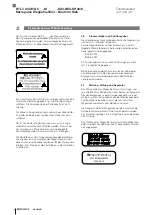
Страница 140: ...必须将设置盒从机组中移除 2 6 插拔连接器和位置传感器 可用的插拔连接器和位置传感器参见章节 11 配件 对于带有插头接口的位移传感器 仅对下列带有出厂预制 电缆的插拔连接器进行了检测和许可 BKS S 32M _ _ BKS S 33M _ _ 仅允许使用章节 11 配件 中许可的位置传感器规格 使用其他连接插头 电缆或位置传感器时必须根据防爆要 求由运营方确保其适用性 2 7 维护 检测和维修 位移传感器的测量原理是无需维护 无磨损 运营方必须 在考虑使用环境和环境影响的情况下 定期检查是否存在 损坏或故障 在这种情况下 必须立即停止运行位移传感 器 仅可由 Balluff GmbH 的服务技术人员维修损坏的位移传 感器 出于安全原因 禁止运营方进行干预或篡改 不得打开或松开位移传感器的外壳 因此 在外壳间隙处 贴有该警告标签 開けないでください Não abrir Не вскры...

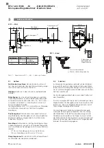
Страница 141: ... 不同结构的位置传感器 可单独订购 参见第 23 页上 的配件 额定长度 定义可提供的位移 长度测量范围 根据各位移 传感器的规格结构 可提供额定长度为 25 mm 至 5500 mm 的杆 Ø 10 2 mm 额定长度为 25 mm 至 5500 mm Ø 8 mm 额定长度为 25 mm 至 1016 mm 缓冲区 杆端不可测量的区域 可穿越行驶 3 2 功能 导波管位于微脉冲位移传感器中 外面套有不锈钢管 起 保护作用 位置传感器沿波导管运动 位置传感器连在设 备构件上 应确定其位置 位置传感器定义在波导管上需要测量的位置 在内部产生的 INIT 脉冲与位置传感器的磁场一起在波导 管中触发一个扭力轴 该扭力轴是通过磁致伸缩产生的并 以超声波速度前进 驶向波导管末端的扭力轴在缓冲区中被吸收 驶向波导管 始端的扭力轴在接收线圈中产生一个电子信号 通过轴的 运行时间确定位置 视设备型号不同...

Страница 142: ...图 4 2 在可磁化材料中的安装类型 杆径 孔径 D2 10 2 mm 至少 13 mm 8 mm 至少 11 mm 表 4 1 在安装到液压缸中时的孔径 4 2 准备安装 安装类型 建议将不可磁化的材料用于夹持位移传感器和 位置传感器 水平安装 额定长度 500 mm 时 必须对杆提供支承 必要时在尾端旋紧 仅针对直径为 10 2 mm 时 液压气缸 安装到液压缸中时必须确保夹持活塞达到最小 孔径 参见 表 4 1 配合孔 BTL 外壳的设备表面必须完全位于传感接收平面 上 所配 O 形环必须将孔完全密封 即 O 形环的锪孔 必须图 4 3制造为与孔相匹配 图 4 3 用于安装带 O 形环的 BTL 的配合孔 位置传感器 可为 BTL7 位移传感器提供不同的位置传感 器 参见配件 页码 23 4 安装和连接 配合孔 O 形环 15 4 2 1 的 锪孔 BTL7 A C E G5_ _ ...

Страница 143: ...较大负载压力的面积相应减小 在安装到液压缸中时 额定长度大于 500 mm 为了防 止杆端磨损 建议安装一个滑动元件 液压缸生产商负责确定详细解决方案的尺寸 滑动元件的材料必须同负载情况 所用的介质和所产生的 温度相匹配 可选材料例如 Torlon 特氟龙或青铜 图 4 4 滑动元件 位置指示器 示例 1 利用滑动元件安装位移传感器 滑动元件可通过旋紧或粘贴的方式进行固定 防止螺丝松动或丢失 选择适当的粘合剂 滑动元件 杆 活塞杆 流出口 图 4 5 滑动元件的细节图和俯视图 在滑动元件和活塞孔之间必须为液压油的流动留有足够大 的缝隙 固定位置传感器的可选方法 螺钉 螺纹环 压入件 刻槽 造粒 当装入液压缸时 位置传感器不得在杆上滑 动 为了达到完美的杆导向效果 隔离环的孔必须与滑动元件 相匹配 图 4 6 隔离环 位置指示器 位置传感器的固定 位置传感器的固定 第 图 4 7 页的 12...

Страница 144: ...6 BU 蓝色 GND2 7 BN 棕色 10 30 V 8 WH 白色 Lb 编程输入 1 未分配的芯线可与控制器的地线连接 但不允许与屏蔽装置连接 2 供电电压和 EMC GND 间的参考电位 3 电压输出可显示平衡电流输出的最小补偿 表 4 2 连接布局 BTL7 SR32 K_ _ 4 5 屏蔽与布线 接地的定义 位移传感器和配电柜接地必须处于等电势 屏蔽 为确保电磁兼容性 EMC 请务必遵守下列说明 位移传感器与控制器采用电磁屏蔽电缆连接 屏蔽 单根铜质金属线制成的编制网 至少覆盖 85 的面积 插头规格 屏蔽装置从内部与插头外壳连接 电缆规格 在位移传感器一侧的电缆线屏蔽装置与壳 体连接 控制器一侧的电缆线屏蔽装置接地 通过保护导体连 接 磁场 本位置测量系统为一种磁性测量系统 请务必注意位移传感器与外部强磁场保持足够的距离 布线 位移传感器 控制器和电源之间的电缆不允许靠近强...

Страница 145: ...从而可能造成人员伤害或财产损失 因此相关人员必须远离设备的危险区域 仅允许由已受培训的专业人员进行设备的调试运 行 请务必遵守设备或系统制造商的安全说明 1 检查固定插座上的接口和电极是否正确 更换破损接 口 2 接通系统 3 检查测量值和可调参数 如有必要 重新调整位移传 感器 尤其是在更换位移传感器或进行维修后由生产 商检查零点和终点的数值是否正确 5 2 运行说明 请定期检验位移传感器及所有连接元件的功能 位移测量系统如出现功能故障请立即停止运行 防止未经授权使用本设备 BTL7 A C E G5_ _ M_ _ _ _ K 8 NEX SR32 K_ _ 微脉冲位移传感器 杆状结构 防爆类型 ec 和 tb ...

Страница 146: ...6 表 6 1 示教功能和反向数值表 6 1 编程输入 设置时必须使用编程输入 La 和 Lb 10 至 30 V 的编程输 入相当于激活 高活跃 为此可使用 Balluff 设置盒 BTL7 A CB02 K 参见第 24 页上的的配件 自动取消激活 如果编程输入超过约 10 分钟未传输信号 则编 程模式自动结束 6 2 调节过程提示 前提条件 编程输入已连接 位移传感器与设备控制系统已连接 可对位移传感器的电压值或电流值进行读取 通过万 用表 设备控制系统或设置盒 图 6 1 连接设置盒 BTL7 A CB02 S 6 调节方法 零点和终点值 位置传感器上的任意位置均可作为零点或终点 但零 点和终点不可互换 绝对零点和终点必须处于所给出的最大或最小极限内 参见数值表 无论调节过程是通过编程输入进行结束或 10 分 钟后自动结束 始终储存最后所调节的数值 示教功能和反向数值表 下列调节示...

Страница 147: ...示教功能操作方法的详细说明参见第 17 页 操作流程 将位置传感器推入新的零点位置 激活编程输入读入新零点 当前终点仍保留 新零点 调节前 调节后 图 6 2 读入新零点 将位置传感器推入新的终点位置 激活编程输入读入新终点 当前零点仍保留 6 调节方法 接上页 新终点 调节前 调节后 图 6 3 读入新终点 仅在 BTL7 C E 中 通过激活编程输入可以使电流输出的特征曲线反向 例如输出的上升特征曲线变为下降特征曲线 不会 使电压输出反向 BTL7 A C E G5_ _ M_ _ _ _ K 8 NEX SR32 K_ _ 微脉冲位移传感器 杆状结构 防爆类型 ec 和 tb ...

Страница 148: ... 120615000xxxxx xx 以上的序列号才能校准 操作流程 将位置传感器推入新的初始位置 激活编程输入读入新起点 通过激活编程输入调节所需的初始值 新零点 调节前 调节后 图 6 4 校准新初始值 将位置传感器推入新的终点位置 激活编程输入读入新终点 通过激活编程输入调节所需的终点值 新终点 调节前 调节后 图 6 5 校准新终点值 6 3 3 复位 在出厂调节时即对位移传感器进行复位 关于复位操作方法的详细说明参见第 20 页 新初始值 新终点值 BTL7 A C E G5_ _ M_ _ _ _ K 8 NEX SR32 K_ _ 微脉冲位移传感器 杆状结构 防爆类型 ec 和 tb ...

Страница 149: ...点 将位置传感器放置在新的零点 1 04 V 4 82 mA 激活 a 至少 2 s 2 s a 新的零点已调节 0 00 V 4 00 mA 调节终点 将位置传感器放置在新的终点 9 89 V 19 13 mA 激活 b 至少 2 s 2 s b 已设置新的终点 10 00 V 20 00 mA 使特征曲线反向 仅在 BTL7 C E 中 同时激活 a 和 b 至少 4 s 4 s a b 3 60 mA 显示错误值 松开后会使输出特征曲线反向 14 85 mA 结束示教功能 同时短时间激活 a 和 b 1 s 1 s a b 10 50 V 3 60 mA 输出端在激活期间输出错误值 显示出当前位置值 10 00 V 4 00 mA 可任意选择设置的各个步骤 可随时结束示教 功能 编程电缆 La a 编程电缆 Lb b BTL7 A C E G5_ _ M_ _ _ _ K 8 NEX...

Страница 150: ...次显示当前位置值 5 39 V 9 15 mA 校准初始值 将位置传感器放置在新的起点 1 04 V 4 82 mA 激活 a 至少 2 s 2 s a 将新起点设置为最后的有效初始值 0 00 V 4 00 mA 校准初始值 通过 a 和 b 可对初始值进行更改 特征曲线的斜度 改变 参见第 16 页 0 00 V 4 00 mA 0 90 V 7 20 mA 结束调节过程 同时短时间激活 a 和 b 1 s 1 s a b 2 00 V 6 00 mA 已储存了所调节的位置值 0 90 V 7 20 mA 设置终点 校准终点值以及结束校准 参见第 19 页 可任意选择设置的各个步骤 可随时结束校 准 a a b b BTL7 A C E G5_ _ M_ _ _ _ K 8 NEX SR32 K_ _ 微脉冲位移传感器 杆状结构 防爆类型 ec 和 tb ...

Страница 151: ...点值 10 00 V 20 00 mA 校准终点值 通过 a 和 b 可对终点值进行更改 特征曲线的斜度 改变 参见页码 16 10 00 V 20 00 mA 8 00 V 16 80 mA 结束调节过程 同时短时间激活 a 和 b 1 s 已储存了所调节的位置值 1 s a b 2 00 V 6 00 mA 8 00 V 16 80 mA 结束校准 同时短时间激活 a 和 b 1 s 1 s a b 10 50 V 3 60 mA 松开后会显示当前位置值 7 63 V 18 56 mA 可任意选择设置的各个步骤 可随时结束校 准 BTL7 A C E G5_ _ M_ _ _ _ K 8 NEX SR32 K_ _ 微脉冲位移传感器 杆状结构 防爆类型 ec 和 tb ...

Страница 152: ...显示的数值 示例 在 0 10 V 时 在 4 20 mA 时 5 39 V 9 15 mA 激活复位 同时激活 a 和 b 至少 4 s 4 s a b 10 50 V 3 60 mA 复位 同时激活 a 和 b 至少 4 s 4 s a b 0 00 V 4 00 mA 激活后 所有数值已复位 9 89 V 19 13 mA 显示出当前位置值 复位被禁用 取消复位 在激活复位步骤后可以无修改地取消复位 同时短时间激活 a 和 b 1 s 1 s a b 显示出当前位置值 BTL7 A C E G5_ _ M_ _ _ _ K 8 NEX SR32 K_ _ 微脉冲位移传感器 杆状结构 防爆类型 ec 和 tb ...

Страница 153: ...击负载 持续冲击 根据 EN 60068 2 272 3 150 g 6 ms 150 g 2 ms 振动 根据 EN 60068 2 62 3 20 g 10 2000 Hz 防护类别根据 IEC 60529 插头 SR32 拧紧螺丝的状态下 IP67 电缆 K_ _ IP682 10 3 供电 外部 稳定电压 BTL7 _5_ _ 10 30 V DC 电压脉动 0 5 Vss 电流消耗 在 24 V DC 时 120 mA 启动峰值电流 500 mA 反极性保护3 最大 36 V 过压保护 最大 36 V 抗电强度 朝向外壳接地 500 V AC 10 4 输出端 BTL7 A 输出电压 载荷电流 0 10 V 和 10 0 V 5 mA BTL7 C 输出电流 载荷电阻 0 20 mA 20 0 mA 500 Ω BTL7 E 输出电流 载荷电阻 4 20 mA 20 4 mA 5...

Страница 154: ... Ø 10 2 mm 的情况 下 25 5500 mm 重量 与长度有关 约 2 kg m 外壳材料 不锈钢 法兰材料 不锈钢 杆材料 不锈钢 杆壁厚 在直径 Ø 8 mm 的情况下 0 9 mm 在直径 Ø 10 2 mm 的情况 下 2 mm 固定外壳 有 6 个孔的法兰 BTL7 K_ _ 电缆材料 PUR 电缆直径 最大 7 mm 允许的弯曲半径 固定布线 35 mm 10 技术参数 接上页 BTL7 A C E G5_ _ M_ _ _ _ K 8 NEX SR32 K_ _ 微脉冲位移传感器 杆状结构 防爆类型 ec 和 tb ...

Страница 155: ...位置传感器的安装尺寸 BTL P 1013 4R BTL P 1013 4S BTL P 1012 4R BTL P 1014 2R 重量 15 g 外壳 铝 包含在型号为 BTL P 1013 4R BTL P 1013 4S BTL P 1012 4R 的位置传感器的供货范围中 间隔垫片 8 mm 材料为聚甲醛 POM BTL P 1028 15R 用于带用于支承管的特种配件 重量 约 68 g 外壳 铝 图 11 2 Ø 4 3 120 Ø 28 Ø 54 Ø 65 8 特殊附件 BTL P 1028 15R 11 配件 BTL7 A C E G5_ _ M_ _ _ _ K 8 NEX SR32 K_ _ 微脉冲位移传感器 杆状结构 防爆类型 ec 和 tb ...

Страница 156: ...长度 5 m 图 11 4 Ø 18 31 37 2 Ø 20 54 Ø max 7 插拔连接器 BKS S 33M _ _ 图 11 5 插拔连接器 BKS S 33M _ _ 输出 针脚 颜色 1 YE 黄色 2 GY 灰色 3 PK 粉红色 4 RD 红色 5 GN 绿色 6 BU 蓝色 7 BN 棕色 8 WH 白色 表 11 1 针脚分配 BKS S 32 33M _ _ 11 3 设置盒 BTL7 A CB02 S32 订购代码 BAE0043 供货范围 设置盒 2 根适配器电缆 分别约为 0 3 m 简要说明 BTL7 A CB02 K 订购代码 BAE0040 供货范围 设置盒 2 根适配器电缆 分别约为 0 3 m 0 6 m 简要说明 11 配件 接上页 BTL7 A C E G5_ _ M_ _ _ _ K 8 NEX SR32 K_ _ 微脉冲位移传感器 杆状结构 ...

Страница 157: ... 00 上升 例如 C_00 0 20 mA 仅在 BTL7 C E 中 10 上升 下降 例如 A_10 10 0 V 和 0 10 V 仅在 BTL7 A G 中 70 下降 例如 C_70 20 0 mA 仅在 BTL7 C E 中 额定长度 4 位 M0500 公制单位为 mm 额定长度 500 mm M0025 M1016 K8 M0025 M5500 K 杆固定类型 K 有 6 个孔的法兰 O 形环 杆径 10 2 mm K8 有 6 个孔的法兰 O 形环 杆径 8 mm 电气连接 径向 SR32 插头 M16 8 芯 符合 IEC 130 9 标准 K_ _ 电缆 径向 例如 K05 5 m BTL7 A C E G5_ _ M_ _ _ _ K 8 NEX SR32 K_ _ 微脉冲位移传感器 杆状结构 防爆类型 ec 和 tb ...

Страница 158: ...0 31496063 9 0 35433071 10 0 393700787 表 13 1 毫米 英寸换算表 1 英寸 25 4 毫米 英寸 毫米 1 25 4 2 50 8 3 76 2 4 101 6 5 127 6 152 4 7 177 8 8 203 2 9 228 6 10 254 表 13 2 英寸 毫米换算表 13 附录 13 2 铭牌 1 订购代码 2 型号 3 序列号 YYMMDDSSSSSSSS CC 图 13 1 铭牌 BTL7 示例 1 3 3 2 897999_AA ZH B22 保留更改权利 替代 G16 BTL7 A C E G5_ _ M_ _ _ _ K 8 NEX SR32 K_ _ 微脉冲位移传感器 杆状结构 防爆类型 ec 和 tb ...

Страница 159: ......
Страница 160: ...Chengshan Rd 8F Building A Yunding International Commercial Plaza 200125 Pudong Shanghai Phone 86 400 820 0016 Fax 86 400 920 2622 service cn balluff com cn DACH Service Center Germany Balluff GmbH Schurwaldstrasse 9 73765 Neuhausen a d F Phone 49 7158 173 370 service de balluff de Eastern Europe Service Center Poland Balluff Sp z o o Ul Graniczna 21A 54 516 Wrocław Phone 48 71 382 09 02 service p...

Отзывы: