Photoelectric Sensors
Diffuse reflective BOS 21M-...-RH12-.. with BGS
No. 833 340 E
•
Edition 0
503
3
Diffuse reflective with
background supression (BGS)
BOS 21M-PUS-RH12-S4 (PNP)
BOS 21M-NUS-RH12-S4 (NPN)
Safety Advisory
Laser protection regulations
: The transmitter
and the laser light barrier comply with laser
protection class II in accordance with DIN EN
60825-1/94. Therefore no additional protective
measures are necessary for operation.
These Photoelectric Sensors are not suited for
safety related applications.
The CE-Marking means that our products
conform to the requirements of the EC Guidelines
89/336/EWG (EMC) and the EMC Statute.
Testing in our EMC Laboratory, which is accredited by
DATech for Testing of Electromagnetic Compatibility, has
shown that these Balluff products satisfy the EMC
requirements of the following Generic Standards:
−
EN 50 081-2 (Emission) and
−
EN 50 082-2 (Noise Immunity)
Display and operating elements
Yellow LED
Output function indicator: The yellow LED is on when the
output is active.
Bi-color LED:
Stability and error indicator: The LED is green when the
sensor is ready and is working in a reliable range.
The LED flashes alternately red and green if the sensor is
improperly calibrated.
SET button: Holding down the button teaches the sensor.
This can also be accomplished using the Teach-in input.
The SET button is then disabled.
1 Output function indicator (yellow)
2 Stability and error indicator
(green/red)
3 SET push-button
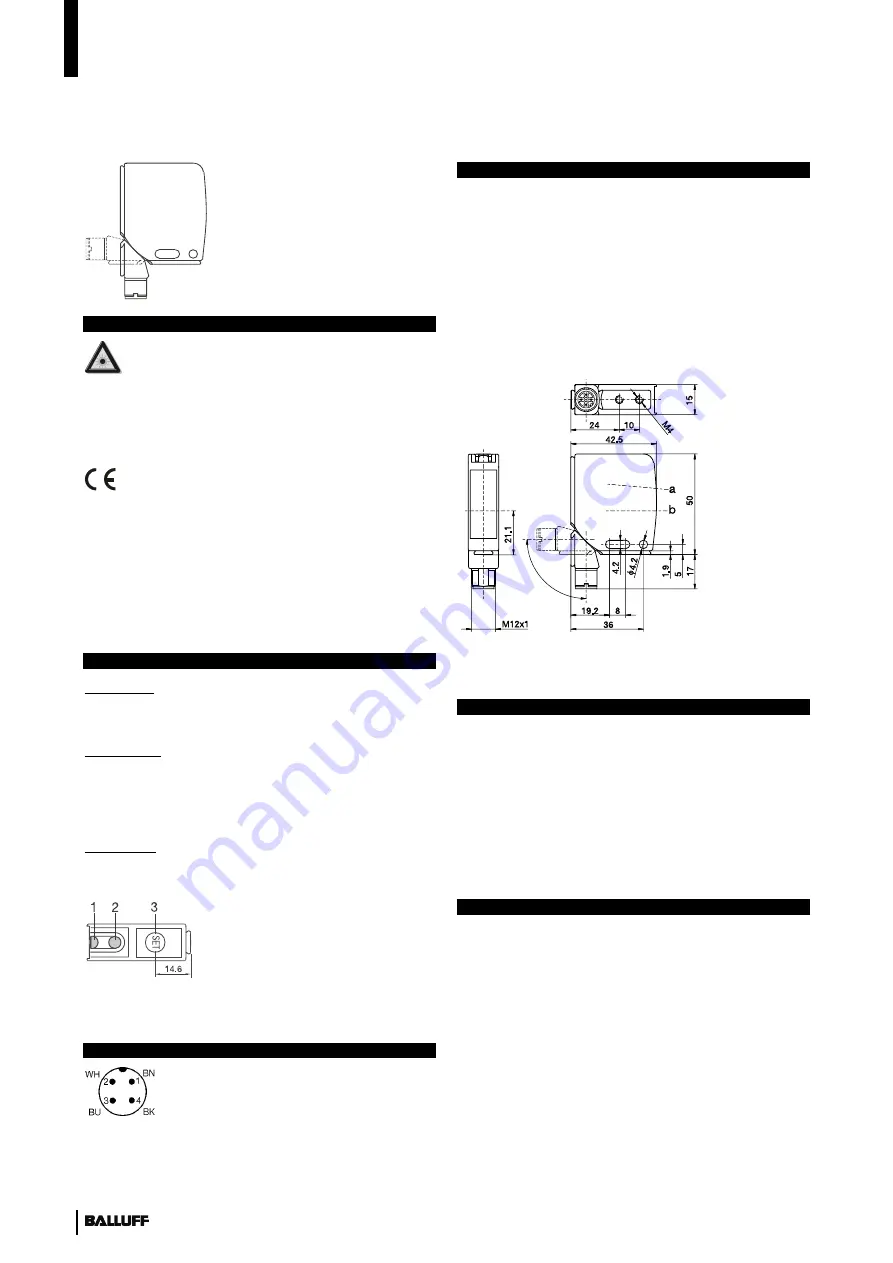
Fig. 1: Display and operating elements
Connections
1 10...30 V DC
2 Teach-In (Connect to 0 V if not
used)
3 0 V
4 Output
Fig. 2: M12 connector
Installation
There are three ways to attach the sensor:
1. Using two screws (M4) and washers through the
housing mounting holes.
2. Using a mounting bracket (available separately).
3. Using special clamps (available separately) and the
dovetail housing profile.
The operating distance is measured from the front surface
of the sensor optics.
The M12 connector can be oriented at four different
ratchet positions of 0°, 90°, 180° or 270°.
a Receiver axis
b Emitter axis
Fig. 3: Dimensions
External Teach-In
The sensor can be calibrated using an exV DC
signal on PIN 2 (Teach-in).
To do this, apply +V DC to the teach-in input before
powering up the sensor. This disables the SET button and
allows external calibration. A +V DC signal then has the
same function as pressing the button.
To restore button function, turn the sensor off, remove the
connection to +V DC (or apply 0V to the pin) and turn the
sensor back on.
Delay function
This function can be used to activate an off-delay of
20 ms.
1. Press the SET pushbutton and keep it pressed until the
bi-color LED turns off, blinks and turns off again. Now
release the button.
If the delay function
is not active
the green LED flashes
with 2 quick pulses over several cycles.
If the delay function
is active
the green LED flashes
with 4 quick pulses over several cycles.
2. To toggle the time delay (turn it on or off), press the
SET button once briefly. The new status is indicated by
the bi-color LED (see Step 1).


