


Balluff Network Interface EtherCAT™, BNI ECT-5x7-005-Z040
www.balluff.com
16
5
Integration
Inputs pin 4
Inputs pin 2
Outputs pin 4
Outputs pin 2
Signal from configured inputs or outputs are depicted in the modules
STD_IN_1bit (input pin 4), input pin 2 as well as
STD_OUT_1bit (output pin 4) and output pin 2.
IO–Link modules
The IO-Link modules always have the same structure:
IOL_I/O_x/xBytes
Number of process data items used (should be equal to or greater
than
the process data length of the IO-Link device)
I = Input data
O = Output data
I/O = Both input and output data
SIO module
When using the SIO module, the port starts n IO-Link mode, then performs
a validation and data retention and then switches to SIO mode.
It is not possible to switch later to IO-Link mode!
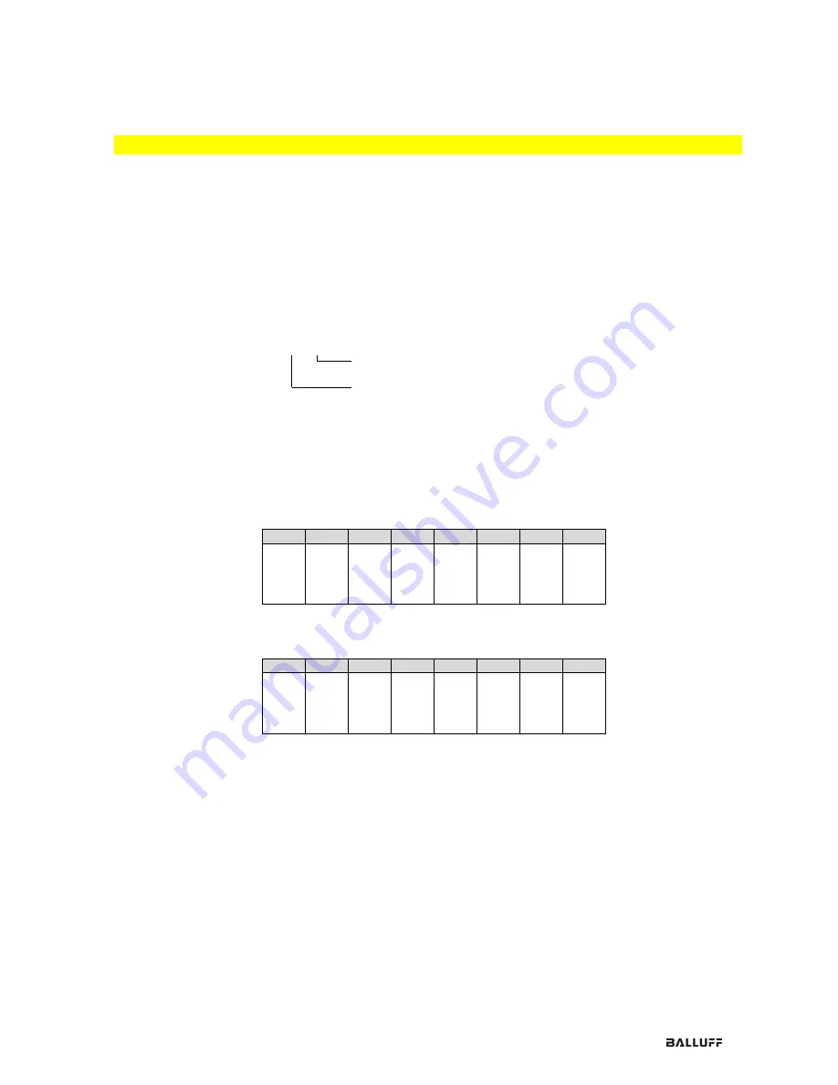
Short-circuit
Pin 4 / Pin 2
Depicts a short circuit between a set output to ground at the respective port pin.
Bit 7
Bit 6
Bit 5
Bit 4
Bit 3
Bit 2
Bit 1
Bit 0
Po
rt
7
Po
rt
6
Po
rt
5
Po
rt
4
Po
rt
3
Po
rt
2
Po
rt
1
Po
rt
0
Restart Pin 4 /
Pin 2 (Class A
only)
If this function is configured, after an actuator short-circuit there is no automatic restart, but
rather the port must be activated by inserting the corresponding bit.
Bit 7
Bit 6
Bit 5
Bit 4
Bit 3
Bit 2
Bit 1
Bit 0
Po
rt
7
Po
rt
6
Po
rt
5
Po
rt
4
Po
rt
3
Po
rt
2
Po
rt
1
Po
rt
0
5.4.
Bit mapping and
function
Bit mapping and function of the configurable modules
Содержание BNI ECT-507-005-Z040
Страница 36: ...www balluff com 35 Notes...


