


www.balluff.com
11
4.2
Assembling the sensor head
DANGER
Uncontrolled system movement
Safety applications: If the magnetic tape unintentionally
comes loose (breakage or offset), this could result in
personal injury and equipment damage.
►
Fasten magnetic tape using a positive locking
method (bolts, groove), in order to prevent
unintentional loosening.
NOTICE!
Interference in function
Improper assembly of the magnetic tape and sensor
head may impair function of the position measuring
system and lead to increased wear or damage to the
system.
►
All permissible distance and angle tolerances (see
section 4.1) must be strictly complied with.
►
The sensor head may not come into contact with
the magnetic tape over the entire measuring range.
Contact must also be avoided if the magnetic tape is
covered by a cover strip (optional).
►
The position measuring system must be installed in
accordance with the indicated degree of protection.
External magnetic fields change the functional properties.
Magnetic fields with ≥ 1 mT reduce the precision of the
system, magnetic fields of ≥ 30 mT destroy the magnetic
tape. The functionality of the system is no longer
ensured.
►
Direct contact with magnetic clamps or other
permanent magnets must be avoided.
►
Contact with other magnetic tapes (magnetic sides)
must be avoided.
No forces may be exerted on the cable on the housing.
►
Provide the cable with a strain relief.
Assembling the sensor head
►
Fasten the right or left side of the sensor head to the
machine part whose position is to be determined (see
Fig. 3-1 to Fig. 3-3, Fig. 4-1 and Fig. 4-2).
To function correctly, the bottom of the sensor
head must always be above the magnetic tape
(see Distances and tolerances on page 10).
If a screw with strength class 8.8 is screwed in
at least 10 mm, the max. tightening torque is
2.3 Nm (with a tooth lock washer 3.1 Nm).
Secure the screws against unintended
loosening (e.g. with locking paint).
4.3
Electrical connection
The electrical connection is made using a connector. See
Tab. 4-2 for the pin assignment.
Note the information on shielding and cable
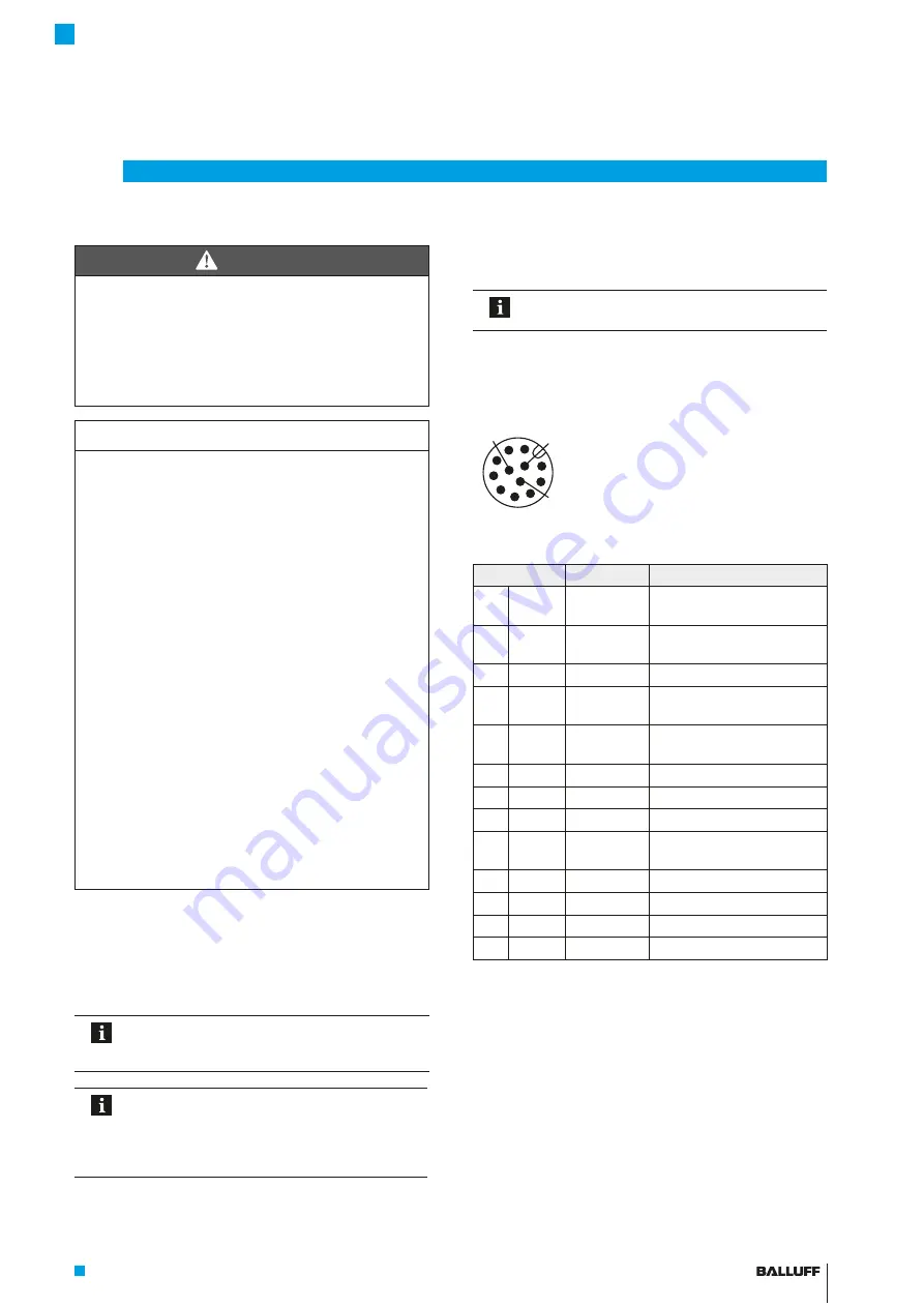
4.3.1 Connector S284
12-wire cable with sense lines (measuring lines) to
compensate for voltage drops in the supply.
Fig. 4-3:
1
10
9
12
8
7
6
5
4
11 3
2
M12 plug pin assignment (view on pin side)
Pin
Signal
Requirements
1
WH
+B (+Cos)
Cosine-shaped voltage
signal
2
BN
−B (−Cos)
Cosine-shaped voltage
signal, inverted
3
GN
+Clk
Clock signal (RS422)
4
YE
−Clk
Clock signal (RS422),
inverted
5
GY
−Data
Data signal (RS422),
inverted
6
PK
+Data
Data signal (RS422)
7
BU
GND
Sensor ground (0 V)
8
RD
U
B
Supply v5 V DC
9
BK
−A (−Sin)
Sine-shaped voltage signal,
inverted
10
VT
+A (+Sin)
Sine-shaped voltage signal
11
GY PK
GND sense GND sense
12
RD BU U
B
sense
U
B
sense
PH
Shield
PE
Connector housing/shield
Tab. 4-2: Pin assignment
4
Installation and connection (continued)
BML-S1H1/2-B/S6 _ C-M3 _ A-D0-KA _ _ , _ -S284
Absolute Magnetically Coded Position Measuring System
english
Содержание BML-S1H1 Series
Страница 1: ...deutsch Betriebsanleitung BML S1H1 B S6_C M3_A D0 KA_ _ _ S284 BML S1H2 B S6_C M3_A D0 KA_ _ _ S284...
Страница 2: ...www balluff com...
Страница 24: ...english User s Guide BML S1H1 B S6_C M3_A D0 KA_ _ _ S284 BML S1H2 B S6_C M3_A D0 KA_ _ _ S284...
Страница 25: ...www balluff com...
Страница 47: ...espa ol Manual de instrucciones BML S1H1 B S6_C M3_A D0 KA_ _ _ S284 BML S1H2 B S6_C M3_A D0 KA_ _ _ S284...
Страница 48: ...www balluff com...
Страница 70: ...fran ais Notice d utilisation BML S1H1 B S6_C M3_A D0 KA_ _ _ S284 BML S1H2 B S6_C M3_A D0 KA_ _ _ S284...
Страница 71: ...www balluff com...
Страница 93: ...Italiano Manuale d uso BML S1H1 B S6_C M3_A D0 KA_ _ _ S284 BML S1H2 B S6_C M3_A D0 KA_ _ _ S284...
Страница 94: ...www balluff com...


