background image

8

english

Product description

4.1 

Dimensions 

Sensor

Supply

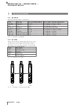
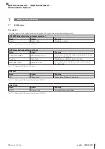
Fig. 4-1:  Dimensions of the amplifier with cable connection (-DP02) in the different views

Sensor

Supply

Fig. 4-2:  Dimensions of the amplifier with plug connection (-S75G und -S75G-SA3) in the different views

BAE SA-OH-061-UA-... / BAE SA-OH-062-IC-...

Photoelectric Sensors

Содержание BAE SA-OH-061-UA-DP02

Страница 1: ...BAE SA OH 061 UA DP02 BAE SA OH 061 UA S75G BAE SA OH 061 UA S75G SA3 BAE SA OH 062 IC DP02 BAE SA OH 062 IC S75G BAE SA OH 062 IC S75G SA3 deutsch Betriebsanleitung english User s guide ...

Страница 2: ...www balluff com ...

Страница 3: ...Betriebsanleitung deutsch BAE SA OH 061 UA DP02 BAE SA OH 061 UA S75G BAE SA OH 061 UA S75G SA3 BAE SA OH 062 IC DP02 BAE SA OH 062 IC S75G BAE SA OH 062 IC S75G SA3 ...

Страница 4: ...www balluff com ...

Страница 5: ...geelemente 9 4 4 Bedruckungen 9 5 Einbau und Anschluss 10 5 1 Einbau 10 5 2 Elektrischer Anschluss 10 5 3 Schirmung und Kabelverlegung 10 6 Inbetriebnahme und Betrieb 11 6 1 Inbetriebnahme 11 6 2 Hinweise zum Betrieb 11 6 3 Wartung 11 7 Menüstruktur 12 7 1 Status View 13 7 2 Signalerfassung Signal Acquisition 14 7 2 1 Beschreibung 14 7 2 2 Teach Verfahren 14 7 3 Teach 14 7 3 1 Teach Menü 14 7 3 2 ...

Страница 6: ...tur und Entsorgung 20 8 1 Reparatur 20 8 2 Entsorgung 20 9 Technische Daten 21 9 1 Allgemeine Merkmale 21 9 2 Umgebungsbedingungen 21 9 3 Elektrische Merkmale 21 9 4 Elektrischer Anschluss 21 9 5 Ausgang Schnittstelle 21 9 6 Material 21 9 7 Mechanische Merkmale 21 9 8 Zulassungen und Kennzeichnungen 21 10 Typenschlüssel 22 BAE SA OH 061 UA BAE SA OH 062 IC Optoelektronische Sensoren ...

Страница 7: ...rklärung Entsorgung Montageanleitung 1 3 Verwendete Symbole und Konventionen Einzelne Handlungsanweisungen werden durch ein vorangestelltes Dreieck angezeigt Handlungsanweisung 1 Handlungsabfolgen werden nummeriert dargestellt 1 Handlungsanweisung 1 2 Handlungsanweisung 2 Zahlen ohne weitere Kennzeichnung sind Dezimalzahlen z B 23 Hexadezimale Zahlen werden mit vorangestell tem 0x dargestellt z B ...

Страница 8: ...n Anwendungen in denen die Personensicherheit von der Gerätefunktion abhängt in explosionsgefährdeten Bereichen im Lebensmittelbereich 2 3 Allgemeine Sicherheitshinweise Tätigkeiten wie Einbau Anschluss und Inbetriebnahme dürfen nur durch geschulte Fachkräfte erfolgen Eine geschulte Fachkraft ist wer aufgrund seiner fachli chen Ausbildung seiner Kenntnisse und Erfahrungen sowie seiner Kenntnisse d...

Страница 9: ...ohlenes Zubehör finden Sie unter www balluff com auf der Produktseite 3 2 Transport Produkt in Originalverpackung bis zum Verwendungs ort transportieren 3 3 Lagerbedingungen Produkt in Originalverpackung lagern Umgebungsbedingungen beachten siehe Umge bungsbedingungen auf Seite 21 3 Lieferumfang Transport und Lagerung BAE SA OH 061 UA BAE SA OH 062 IC Optoelektronische Sensoren ...

Страница 10: ... 4 1 Abmessungen der Verstärker mit Kabelanschluss DP02 in den verschiedenen Ansichten Sensor Versorgung Bild 4 2 Abmessungen der Verstärker mit Steckeranschluss S75G und S75G SA3 in den verschiedenen Ansichten BAE SA OH 061 UA BAE SA OH 062 IC Optoelektronische Sensoren ...

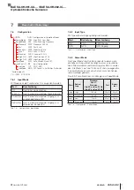
Страница 11: ...rte 2 SIG Gelb Status Ausgang 3 Alarm Rot Alarmstatus Teachstatus 4 PWR Grün Das Gerät ist betriebsbereit 5 SYNC Orange Synchronisation aufgebaut 6 Taster Multifunktionstaste zurück im Menü Bild schirm aus Anzeige Easy Teach 3 s gedrückt halten 7 Tippschalter Menüpunkt weiterblättern oder Wert erhöhen Bei längerem Betätigen der Taste wird ein Wert schnelldurchlauf aktiviert Tippschalter Bestätigun...

Страница 12: ...ausgang 4 20 mA Rosa IN Eingang externer Teach 3 Pol Sensor alle Versionen 1 LED Sender LED 3 FT Empfänger Fototransistor 4 GND 0 V Kabelschirm Tab 5 1 Pinbelegung Werkseinstellung Standard Power Standard Speed Syncmode Off Input Off 5 3 Schirmung und Kabelverlegung Das Sensorkabel ist geschirmt und sollte nicht verlängert werden 5 1 Einbau Abmessungen siehe Bilder auf Seite 8 Folgende Befestigung...

Страница 13: ...s beachten 1 Anschlüsse auf festen Sitz und richtige Polung prüfen Beschädigte Anschlüsse tauschen 2 System einschalten 3 Signalwerte und einstellbare Parameter prüfen und ggf den Sensor neu ausrichten und einstellen Insbesondere nach dem Austausch des Sensors oder der Reparatur durch den Hersteller die korrekten Werte prüfen 6 2 Hinweise zum Betrieb Funktion des Sensors und aller damit verbundene...

Страница 14: ...Fact Reset DEF No Yes CONFIG CON Configuration of Operation Modes PowerMode POW High Std Low Xlow SpeedMode SPE Max Switching Frequency Standard STSP Standard 1000 Hz Fast FASP Fast 4 kHz Superfast SFSP Superfast 8 kHz Sync 7 SYN7 Sync 7 500 Hz Precision PRSP Precision 125 Hz High Pr 25 H2SP High Precision 25 Hz High Pr 30 H3SP High Precision 30 Hz SyncMode SYN Auto Master Slave Off InputConf 3 IN...

Страница 15: ...ion 25Hz H3SP High precision 30Hz 2 Power mode HIPW High power STPW Standard power LOPW Low power XLPW Extra low power 3 Lock Lock active 4 Signal value Measured signal value 5 TP Teach point 6 Amplification Amplifier amplification 7 Output value Output current 8 Output value Output voltage 9 Input mode In_Off Input Off Teach Teach In En_Em Enable emitter Dis_Em Disable emitter Input type P PNP N ...

Страница 16: ...each in sowie für das direkte Setzen eines Setpoints muss folgende Bedingung erfüllt sein Der zu teachende Setpoint muss sich im Gültigkeitsbereich des Signals befinden Ein aktiver Teach Vorgang wird durch Leuchten der roten LED angezeigt Blinkt die rote LED ist der aktuell anlie gende Signalwert außerhalb des Gültigkeitsbereichs Single Value Teach Beim Single Value Teach wird der Arbeitspunkt Ope...

Страница 17: ... Im Standard Mode entspricht der Amplification Range dem hardwaremäßig eingestellten Verstärkungsfaktor Im Advanced Mode wird die Verstärkung zusätzlich rechne risch erhöht Standard Amplification 10 256 Advanced Amplification 10 1000 7 4 2 Teach Point Hiermit wird der beim Teachvorgang gewünschte Teach Point gewählt Verstärker Variante Teach Point BAE SA OH 61 UA 5 V 8 V 9 V 10 V BAE SA OH 62 IC 5...

Страница 18: ...en wird empfohlen die Standby Power auf always off oder on with touch zu setzten OPTIONS OPT Options Lock Param PLC Lock OFF Lock ON Conf EasyT ETE Off 1 V Teach Display DIS Display Settings Brightness BRI Low Medium High Orientation ORI NoRotation 180 CW Rot Stb Visib STB always on always off on w touch ShdwnTimer SHD Standby Shutdown Timer 5 60 600 s Fact Reset DEF No Yes 7 Menüstruktur Fortsetz...

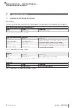
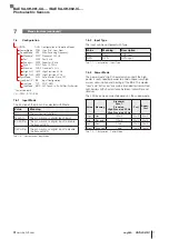
Страница 19: ...YN Auto Master Slave Off InputConf 3 INP Input Configuration Inp Type TYP PNP NPN Inp Mode MOD Off Teach In En Emitter DisEmitter 7 Menüstruktur Fortsetzung 7 6 2 Input Type Mit Type kann der Eingang konfiguriert werden Wert Bedeutung Beschreibung PNP PNP PNP Eingang NPN NPN NPN Eingang Tab 7 7 Configuration Input Type 7 6 3 Power Mode Der Power Mode High sollte nur genutzt werden wenn die hohe Le...

Страница 20: ...5 Hz 2 1 x Master 1 x Slave High Pr 30 High Precision 30 Hz 30 Hz 2 1 x Master 1 x Slave Tab 7 9 Configuration Speed Mode 7 6 5 Sync Mode Der Sensor kann mit anderen Sensoren synchronisiert werden Dabei kann der BAE sowohl die Rolle des Masters als auch die des Slaves einnehmen Der Master muss sich immer rechts befinden Die Syn chronisierung erfolgt durch eine Infrarot Schnittstelle Wert Beschreib...

Страница 21: ... Der Sensor befindet sich im Teach in Modus und es ist kein Objekt sichtbar Teachen ist nicht möglich Teach in Rot statisch Das Gerät befindet sich gerade im Teach in Modus Bad Signal Quality Rot Puls 50 ms Schlechte Signalqualität die Signalqualität befindet sich unterhalb der Warnschwelle Tab 7 12 Bedeutung der LED Zustände LED Alarm LED SIG Name Signal Bedeutung SIG Gelb statisch Status Signal ...

Страница 22: ...Produkt defekt sein nehmen Sie Kontakt mit unserem Service Center auf 8 2 Entsorgung Befolgen Sie die nationalen Vorschriften zur Entsor gung Weitere Informationen finden Sie unter www balluff com auf der Produktseite 8 Reparatur und Entsorgung BAE SA OH 061 UA BAE SA OH 062 IC Optoelektronische Sensoren ...

Страница 23: ... kHz Kurzschlussschutz ja Vertauschmöglichkeit geschützt ja Verpolungssicher ja 9 4 Elektrischer Anschluss Anschluss Stecker M8x1 Kabel 2m Anzahl Pins 4 Stecker 5 Kabel 9 5 Ausgang Schnittstelle Ausgang Pin 4 schwarz Analogausgang Analogausgang 4 20 mA 062 IC 0 10 V 061 UA Eingang Pin 2 weiß Analog GND S75G DP02 digitaler Eingang S75G SA3 Digitaler Eingang umschaltbar PNP NPN S75G SA3 Kabelvariant...

Страница 24: ...er Optischer Sensor BAE SA OH 0 Balluff Accessory Electronical Ausgang UA Analog Spannungsausgang 0 10V IC Analog Stromausgang 4 20mA Elektrischer Anschluss Versorgung S75G Stecker 4 polig M8 DP02 Kabel Zugentlastung 2m PUR Kabel Nr 953141_AA DE E22 Änderungen vorbehalten BAE SA OH 061 UA BAE SA OH 062 IC Optoelektronische Sensoren ...

Страница 25: ...User s Guide english BAE SA OH 061 UA DP02 BAE SA OH 061 UA S75G BAE SA OH 061 UA S75G SA3 BAE SA OH 062 IC DP02 BAE SA OH 062 IC S75G BAE SA OH 062 IC S75G SA3 ...

Страница 26: ...www balluff com ...

Страница 27: ...elements 9 4 4 Labelings 9 5 Installation and connection 10 5 1 Installation 10 5 2 Electrical connection 10 5 3 Shielding and cable routing 10 6 Startup and operation 11 6 1 Startup 11 6 2 Operating notes 11 6 3 Maintenance 11 7 Menu structure 12 7 1 Status View 13 7 2 Signal Acquisition 14 7 2 1 Description 14 7 2 2 Teach Methods 14 7 3 Teach 14 7 3 1 Teach Menu 14 7 3 2 Amplification 14 7 4 Con...

Страница 28: ...8 Repair and disposal 20 8 1 Repair 20 8 2 Disposal 20 9 Technical data 21 9 1 General feature 21 9 2 Ambient conditions 21 9 3 Electrical data 21 9 4 Electrical connection 21 9 5 Output Interface 21 9 6 Materials 21 9 7 Mechanical features 21 9 8 Approvals and designations 21 10 Type codes 22 BAE SA OH 061 UA BAE SA OH 062 IC Photoelectric Sensors ...

Страница 29: ... fol lowing documents Data sheet Declaration of conformity Disposal Assembly instructions 1 3 Symbols and conventions Individual action instructions are indicated by a preceding triangle Instruction 1 Action sequences are numbered consecutively 1 Instruction 1 2 Instruction 2 Numbers unless otherwise indicated are decimals e g 23 Hexadecimal numbers are represented with a preceding 0x e g 0x12AB N...

Страница 30: ...ented applications in which personal safety depends on the device function In explosive atmospheres in the food sector 2 3 General safety notes Activities such as installation connection and commis sioning may only be carried out by qualified personnel Qualified personnel are persons whose technical trai ning knowledge and experience as well as knowledge of the relevant regulations allow them to a...

Страница 31: ...d separately Recommended accessories can be found at www balluff com on the product page 3 2 Transport Transport product to location of use in original packaging 3 3 Storage conditions Store product in original packaging Observe ambient conditions see Ambient conditions on page 21 3 Scope of supply transport and storage BAE SA OH 061 UA BAE SA OH 062 IC Photoelectric Sensors ...

Страница 32: ...pply Fig 4 1 Dimensions of the amplifier with cable connection DP02 in the different views Sensor Supply Fig 4 2 Dimensions of the amplifier with plug connection S75G und S75G SA3 in the different views BAE SA OH 061 UA BAE SA OH 062 IC Photoelectric Sensors ...

Страница 33: ...atus 4 PWR Green The device is ready for operation 5 SYNC Orange Synchronization established 6 Button Multifunction button Back in menu screen off display Easy Teach hold down for 3 s 7 Switch Scroll through menu items or increase value Pressing and holding the button causes the values to scroll through quickly Switch Confirmation or parameter transfer Switch Scroll through menu item or decrease v...

Страница 34: ...rrent output 4 20 mA Rosa IN Input external teach 3 pin sensor all versions 1 LED Emitter LED 3 PHT Receiver Photo transistor 4 GND 0 V Cable shielding Tab 5 1 Pin Assignment Factory setting Standard Power Standard Speed Syncmode Off Input Off 5 3 Shielding and cable routing The BOH sensor cable is shielded and should not be extended 5 1 Installation For dimensions see drawings on page 8 The follo...

Страница 35: ...ns for tightness and correct polarity Replace damaged connections 2 Turn on the system 3 Check measured values and adjustable parameters and realign and adjust the sensor if necessary Check for the correct values especially after repla cing the sensor or after repair by the manufacturer 6 2 Operating notes Regularly check function of the sensor and all associa ted components Take the sensor out of...

Страница 36: ... 60 600 s Fact Reset DEF No Yes CONFIG CON Configuration of Operation Modes PowerMode POW High Std Low Xlow SpeedMode SPE Max Switching Frequency Standard STSP Standard 1000 Hz Fast FASP Fast 4 kHz Superfast SFSP Superfast 8 kHz Sync 7 SYN7 Sync 7 500 Hz Precision PRSP Precision 125 Hz High Pr 25 H2SP High Precision 25 Hz High Pr 30 H3SP High Precision 30 Hz SyncMode SYN Auto Master Slave Off Inpu...

Страница 37: ...25Hz H3SP High precision 30Hz 2 Power Mode HIPW High power STPW Standard power LOPW Low power XLPW Extra low power 3 Lock Lock active 4 Signal Value Measured signal value 5 TP Teach point 6 Amplification Amplifier amplification 7 Output Value Output current 8 Output Value Output voltage 9 Input Mode In_Off Input Off Teach Teach In En_Em Enable emitter Dis_Em Disable emitter Input Type P PNP N NPN ...

Страница 38: ...ll to directly set a setpoint the following conditions must be met The setpoint that is to be taught must be in the validity range of the measurement value signal An active teach process is indicated by illumination of the red LED If the red LED flashes the currently pending measurement value is outside of the validity range Single Value Teach With single value teach the switching point setpoint i...

Страница 39: ...e In standard mode the amplification range corresponds to the amplification factor set in the hardware In advanced mode the amplification is additionally increased by calcu lation Standard Amplification 10 256 Advanced Amplification 10 1000 7 4 2 Teach Point This selects the teach point desired during the teaching process Amplifier version Teach point BAE SA OH 61 UA 5 V 8 V 9 V 10 V BAE SA OH 62 ...

Страница 40: ...the standby power to always off or on with touch OPTIONS OPT Options Lock Param PLC Lock OFF Lock ON Conf EasyT ETE Off 1 V Teach Display DIS Display Settings Brightness BRI Low Medium High Orientation ORI NoRotation 180 CW Rot Stb Visib STB always on always off on w touch ShdwnTimer SHD Standby Shutdown Timer 5 60 600 s Fact Reset DEF No Yes 7 Menu structure continued Display Brightness low mediu...

Страница 41: ... Auto Master Slave Off InputConf 3 INP Input Configuration Inp Type TYP PNP NPN Inp Mode MOD Off Teach In En Emitter DisEmitter 7 Menu structure continued 7 6 2 Input Type The input can be configured with Type Value Meaning Description PNP PNP PNP input NPN NPN NPN input Tab 7 7 Configuration Input Type 7 6 3 Power Mode The power mode High should only be used if the high power is really needed in ...

Страница 42: ...e High Pr 25 High Precision 25 Hz 25 Hz 2 1 x Master 1 x Slave High Pr 30 High Precision 30 Hz 30 Hz 2 1 x Master 1 x Slave Tab 7 9 Configuration Speed Mode 7 6 5 Sync Mode The sensor can be synchronized with other sensors Here the BAE can assume the role of both master and slave The master must always be on the right The synchroniza tion is done by an infrared interface Value Description Auto Sen...

Страница 43: ... 1 1 The sensor is in Teach In mode and no object is visible Teaching is not possible Teach in Red static The device is currently in teach in mode Bad Signal Quality Red pulse 50 ms Poor signal quality the signal quality is below the war ning threshold Tab 7 12 Meaning of LED States LED Alarm LED SIG Name Signal Meaning SIG Yellow static Signal status Signal Teach Point Tab 7 13 Meaning of LED Sta...

Страница 44: ...alluff If the product is defective contact our Service Center 8 2 Disposal Observe the national regulations for disposal Additional information can be found at www balluff com on the product page 8 Repair and disposal BAE SA OH 061 UA BAE SA OH 062 IC Photoelectric Sensors ...

Страница 45: ...1 kHz 8 kHz Short circuit protection yes Protection against miswiring yes Polarity reversal protected yes 9 4 Electrical connection Connection Plug M8x1 Cable 2m Number of pins 4 Plug 5 Cable 9 5 Output Interface Output pin 4 black Analog output Analog output 4 20 mA 062 IC 0 10 V 061 UA Input pin 2 white Analog GND S75G DP02 digital input S75G SA3 Digital input switchable PNP NPN S75G SA3 Cable v...

Страница 46: ... amplifier Optical head BAE SA OH 0 Balluff Accessory Electronical Output UA Analog voltage output 0 10V IC Analog current output 4 20mA Electrical connection supply S75G Plug 4 pin M8 DP02 Cable strain relief 2m PU cable Nr 953141_AA EN E22 Änderungen vorbehalten BAE SA OH 061 UA BAE SA OH 062 IC Photoelectric Sensors ...

Страница 47: ......

Страница 48: ...Chengshan Rd 8F Building A Yunding International Commercial Plaza 200125 Pudong Shanghai Phone 86 400 820 0016 Fax 86 400 920 2622 service cn balluff com cn DACH Service Center Germany Balluff GmbH Schurwaldstrasse 9 73765 Neuhausen a d F Phone 49 7158 173 370 service de balluff de Eastern Europe Service Center Poland Balluff Sp z o o Ul Graniczna 21A 54 516 Wrocław Phone 48 71 382 09 02 service p...

Отзывы: