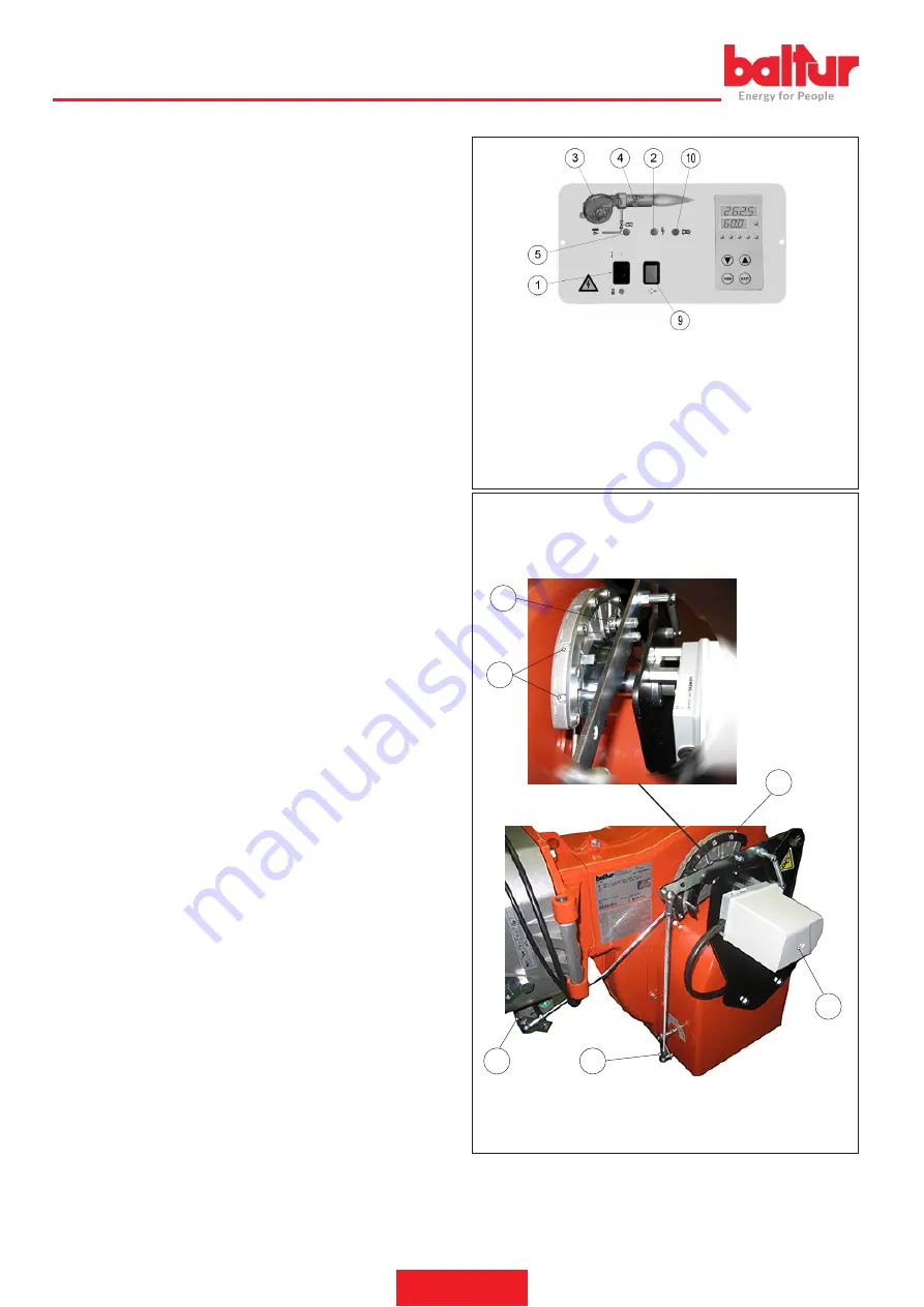
ADJUSTING THE IGNITION POWER
•
Position the first flame air flow rate regulation cam to an opening
angle of 20°-25°. If installed, open the safety valve flow rate regu
-
lator fully.
•
Now switch on the switch (1),(SF) and (S1) and all enabling si
-
gnals, this powers on the control device, and the programmer turns
on the burner as described in the chapter "Operation description".
During the pre-ventilation phase make sure that the pressure swi
-
tch for controlling air pressure switches over. If the air pressure
switch does not detect sufficient pressure, the ignition transformer
is not switched on, nor are the gas valves, therefore the equipment
“locks out” (10).(4).
-
The “lock out” with flame present may be caused by instability
in the ionisation area, due to an incorrect air/gas ratio.
•
Correct the air flow acting on the screw(s) (11), where the bearing
(12) is located:
-
in a clockwise direction the air flow increases
-
in an anticlockwise rotation: the air flow decreases.
•
It may occur that the ionisation current is disturbed by the dischar
-
ge current of the ignition transformer (the two currents have a com
-
mon path on the burner’s “mass”) so the burner locks out due to an
insufficient ionisation. Invert the supply (230V side) of the ignition
transformer.
•
This problem may also be caused by an insufficient “ground con
-
nection” to the burner’s casing.
ADJUSTING THE MAXIMUM POWER
After ignition power adjustment, press the switch on the connector
(4) to maximum.
Check that the electric servomotor second stage
gas flow rate regulation cam is positioned at 120°.
•
To regulate the gas flow operate the valve pressure regulator. Con
-
sult the instructions related to the installed gas valve model. Avoid
keeping the burner running if the heating capacity is greater than
the maximum amount allowed for the boiler, to avoid damaging it.
•
Check the combustion parameters with appropriate instruments
(C02 max= 10%, O2 min=3%, CO max=0,1%)
1 Main on/off switch
2 Thermostat on indicator light
3 Fan motor indicator light
4 Ignition transformer indicator light
5 Gas valves' indicator light
9 Reset button
10 Lock-out warning light
Part_MotReg
01
MotReg_
002
7
6
8
34
12
11
ENGLISH
18 / 34
0006160254_202001
Содержание 17840010
Страница 2: ......
Страница 34: ...SCHEMI ELETTRICI ITALIANO 32 34 0006160254_202001 ...
Страница 36: ...ITALIANO 34 34 0006160254_202001 ...
Страница 68: ...WIRING DIAGRAMS ENGLISH 32 34 0006160254_202001 ...
Страница 70: ...ENGLISH 34 34 0006160254_202001 ...
Страница 71: ......


