background image

3

b. Important, 

once the connector has passed through the center hole, tuck the 

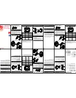
wire harness out of the way by pressing it into the notch hole as shown in figure 9.

c. 

Slide wires through the notch until mounting plate sits flush against door.

d.

 Making sure that 

exterior assembly and cylinder 

are pressed flush 

against exterior door, with Baldwin cylinder logo horizontal, insert mounting 

bolts and tighten.

e.

 Check the vertical alignment 

for mounting plate 

and 

exterior 

assembly. (See figure 10.)

f.

 Test. Using the key, retract and 

extend the bolt a few times to test 

for smooth action.

g.

 If action feels rough, loosen the 

screws and re-align the mounting 

plate and the exterior assembly. 

h.

 Repeat as required.

a. 

Carefully insert the connector of the wire harness - through the center hole of the 

mounting plate (see figure 8). 

5.  Attach the Connector to the Interior Assembly.

Continued 

4.  Install Interior Mounting plate.

a.

 Align the connector with the connector port of the interior assembly, 

matching notch to slot.

Important Note: To prevent damage, always handle the wire harness 

at the connector (do not pull wires).

Fig. 8

Mounting 

Plate

Connector

Notch

Hole

Fig. 10

Bolt

KEEP PARALLEL

Fig. 9

Connector Port

Connector

Connector

Notch

Slot

Interior

Assembly

Top view

horizontal

Содержание 8252 Series

Страница 1: ...mpletely before beginning installation Use the checklist below to assure completion of important steps ATTACH CONNECTOR RUN BOLT DIRECTION DETERMINATION PROGRAM CODE S VERIFY OPERATION Section 5 Secti...

Страница 2: ...inished screws see figure 4 a Remove cover from assembly by sliding cover up and off see figure 5 b Remove the battery case from interior as sembly by lifting the case up and out and set aside see fig...

Страница 3: ...d the bolt a few times to test for smooth action g If action feels rough loosen the screws and re align the mounting plate and the exterior assembly h Repeat as required a Carefully insert the connect...

Страница 4: ...d Route wires down avoiding any excess bulge at curve which could interfere with battery pack installation b Once flush on door insert and tighten small screws to secure assembly onto the mounting pla...

Страница 5: ......

Страница 6: ...erly when it is in the vertical position when unlocked or in the horizontal position when locked 8 Continued 9 Programming a User Code A programmed code can be from four 4 to eight 8 digits long For m...

Страница 7: ...t 30 seconds after unlocking Switch 1 Status LED blinks every 5 seconds when in the ON position Note The low battery RED LED cannot be disabled CAUTION Prevent unauthorized entry This lock can be open...

Страница 8: ...rrect code is entered the unit beeps multiple times for approximately 3 seconds Regardless of switch 1 position under Low Battery condition red LED will flash every 5 seconds 1 The interior LED 2 The...

Страница 9: ...imes c Wait 10 seconds d Insert battery pack e The system should flash the Green LED and beep indicating proper initialization f Repeat a d if initialization failed Q I am planning to be away for seve...

Отзывы: