background image

Section 5

Troubleshooting and Maintenance

Troubleshooting and Maintenance 5-1

MN2412

Maintenance

This manual contains only very minimal engine maintenance instructions. Refer to the engine

manufacturer’s owner’s manual for specific engine maintenance instructions for your generator

set. Any maintenance instructions or recommendations in the engine owner’s manual take

precedence over any of the following general recommendations.

General:

1.

Inspect the fuel system for leaks.  Replace all defective components immediately.

2.

Inspect and replace any fuel line that shows signs of deterioration.

3.

Inspect all fuel clamps to ensure they are tight.

4.

Make sure the fuel cap fits snugly on the fuel tank and that the fuel tank does not leak.

5.

Inspect and clean the battery posts and the associated battery cable terminals.

6.

Inspect the external wire cables and connectors used with the generator set for cuts,

frayed insulation, or loose connections.  Repair or replace damaged parts before use.

7.

The engine should be checked for proper speed setting(s).

Prior to adjusting the engine speed, turn the auto idler switch to “OFF” (if present).

Make sure that the auto idler magnet does not touch the throttle lever of the engine

when running.
a.

Disconnect all electrical loads and start the engine.

b.

Adjust the engine speed to 3720 RPM (62 Hz) with no load speed.

c.

Adjust the auto idler speed after you have accomplished the above adjustment.

d.

Adjust the auto idler speed by moving the electro

magnet back and forth in the

magnet bracket to achieve an engine RPM of 2500

2900 with the auto idler switch

“ON”.

8.

Test all GFCI receptacles monthly by pressing the test button on the receptacle and

making sure that the GFCI trips and and no voltage is present at the receptacle.

Replace any GFCI receptacle that fails the test.

Engine:

1.

Clean and/or replace any fuel, oil, and/or air filters per the engine manufacturers’

guidelines.

2.

Check oil level regularly; at least every 5 to 8 operating hours. Maintain the proper oil

level.

3.

Change the oil as is recommended in the engine manufacturer’s owner’s manual.

4.

Replace the spark plug(s) as is recommended by the engine manufacturer.

5.

Clean the cooling fins on the engine to keep the engine’s heat dissipation potential at

it’s maximum.

6.

Inspect and clean all governor and carburetor linkages so they operate properly.

7.

Inspect the recoil starting rope for any damage and replace it if necessary (if

applicable).

8.

Clean the trash screen around the recoil starter or other cooling air intake.

Alternator:  

( also called Generator End)

This generator set must be run at its proper speed to obtain the correct electrical power at its

output.  All engines have a tendency to slow down when a load is applied to it.  The engine

governor is designed to hold the operating speed as nearly constant as possible. When the

electrical load is increased, the engine is more heavily loaded and engine speed drops slightly.

This slight decrease in engine speed results in a slight decrease in generator voltage and

frequency output. This voltage and frequency variation has no appreciable effect in the operation

of motors, lights, and most appliances and tools. However, timing devices and clocks will not

keep perfect time when used on this generator.

1.

Clean the generator set and remove any and all dust, dirt, or other foreign material.

2.

Inspect and clean the cooling air intake and exhaust louvers of the generator end.

Make sure they are clean.  Remove dirt or any buildup that may restrict the cooling air

flow.

3.

Clean the generator set and its components with a damp cloth or sponge.  

Never use a water hose or pressure washer as this may damage electrical

components.

4.

Inspect and replace any control panel components that are broken or not working

properly (receptacles, circuit breakers, switches, etc.)

Содержание PC Series

Страница 1: ...PowerchiefR POW R Products Generator Series PC Installation Operating Manual 5 05 MN2412...

Страница 2: ...hemicals known to the state of California to cause cancer birth defects and other reproductive harm WARNING CALIFORNIA PROPOSITION 65 WARNING Battery posts terminals and related accessories are known...

Страница 3: ...allation 3 2 Electrical Connections 3 2 Frame Ground Connection 3 3 Engine Oil 3 4 Battery Connections 3 4 Use of Electric Motor Loads 3 5 Optional Wheel Kit 3 6 Recommended Engine Oil and Battery Typ...

Страница 4: ...ii Table of Contents MN2412...

Страница 5: ...ipment at all times Keep non qualified personnel at a safe distance from this equipment Only qualified personnel familiar with the safe installation operation and maintenance of this device should att...

Страница 6: ...should not be attempted Never start the engine unless you have first verified that the installation and operation of the generator are as described in this manual WARNING Be sure that you are complete...

Страница 7: ...starting a battery can cause the battery to explode and cause severe injury or death to anyone in the area WARNING High voltage is present whenever engine is running Electrical shock can cause seriou...

Страница 8: ...et that has been modified or tampered with Be sure that all covers and guards are properly installed and that the unit is safe before starting the engine If you are unsure contact Baldor before starti...

Страница 9: ...of fire and explosion because they generate hydrogen gas Hydrogen gas is extremely explosive Never jump start a battery smoke in the area around the battery or cause any spark to occur in the area aro...

Страница 10: ...ion as designed Caution Do not support the generator from the top of the wrap frame Caution Do not tamper with or change the engine speed Engine speed is factory set to produce the correct voltage and...

Страница 11: ...s If a Baldor Generator repair facility determines that the problem with a Baldor product is not due to defects in Baldor workmanship or materials then the party requesting warranty service will be re...

Страница 12: ...is not scheduled for replacement as required maintenance in the written instructions supplied is warranted for the warranty period If the part fails during the period of warranty coverage the part wi...

Страница 13: ...g guidelines prior to storing the unit 1 Remove all fuel from the engine s fuel tank 2 Start the generator set and allow it to run out of fuel 3 Close all the fuel valves Note An alternative to draini...

Страница 14: ...Installation The generator is completely assembled tested and adjusted at the factory before it is shipped to you External connections required at the time of installation are Note The generator is sh...

Страница 15: ...ceptacle Connections X GOLD G W SILVER NEMA L5 30R 125V 30A GOLD X G W SILVER Y GOLD NEMA L14 30R 125 250V 30A NEMA 5 20R 125V 20A Frame Ground Connection WARNING Be sure the system is properly ground...

Страница 16: ...acts skin or eyes immediately flush the area with water and seek medical attention quickly WARNING A battery presents a risk of electrical shock hazard and high short circuit current The following pre...

Страница 17: ...d is connected to the positive terminal of your battery Use of Electric Motor Loads Electric motors require much more current amperes to start them than to keep them running Some motors particularly s...

Страница 18: ...mended Engine Oil and Battery Type Series PC MODEL SUMMER WINTER OIL RECOMMENDED AMPS COLD MODEL SUMMER OIL WINTER OIL OIL CAPACITY RECOMMENDED BATTERY AMPS COLD CRANKING PC30H 17 10030 SAE 30 5W 30 8...

Страница 19: ...ctric utility must be connected by means of approved transfer switch equipment so as to isolate the electrical circuit from the utility distribution system when the generator is operating Failure to i...

Страница 20: ...attempts 6 Once the engine has started release the start switch and do not re engage it Note If the engine does not start after a few attempts smell for fuel near the air cleaner If there is a signif...

Страница 21: ...est Engine 1 Clean and or replace any fuel oil and or air filters per the engine manufacturers guidelines 2 Check oil level regularly at least every 5 to 8 operating hours Maintain the proper oil leve...

Страница 22: ...t overload Verify all connections are proper and check tighness torque of terminals Replace worn bearing Low output voltage Low engine speed Excessive load High resistance connections connections will...

Страница 23: ...tor windings and cause possible generator damage Operator Panel Configuration Figure A 1 PC30H Operator Panel Duplex Receptacle Duplex receptacle is rated at 125VAC 15 Amps Receptacle Single style rec...

Страница 24: ...02A08 OR Table A 1 Generator Set Parts List Ref No Part No Description PC30H PC40H PC50H PC60H PC90VE 1 HA9139A00 Adaptor X 1 HA9139A01 Adaptor X X X X 2 HA1037A00 C Washer X X X X X 3 61FN3000 Fan X...

Страница 25: ...Fuel Line 1 4 ID Filter to Engine X X X Not Shown EA0012A21 Fuel Line 1 4 ID Tank to Filter X Not Shown EA0012A22 Fuel Line 3 16 ID Tank to Filter X X X Not Shown EA0035A00 Spark Deflector X Not Shown...

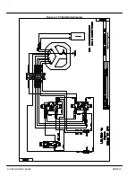
Страница 26: ...A 4 PowerchiefR Series MN2412 Figure A 5 PC30H Wiring Diagram...

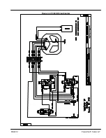
Страница 27: ...PowerchiefR Series A 5 MN2412 Figure A 6 PC40H Wiring Diagram...

Страница 28: ...A 6 PowerchiefR Series MN2412 Figure A 7 PC50H Wiring Diagram...

Страница 29: ...PowerchiefR Series A 7 MN2412 Figure A 8 PC60H Wiring Diagram...

Страница 30: ...A 8 PowerchiefR Series MN2412 Figure A 9 PC90VE Wiring Diagram...

Страница 31: ...arranty on EVAP emission related parts is as follows Any warranted part that is not scheduled for replacement as required maintenance in the written instructions supplied is warranted for the warranty...

Страница 32: ...this product contains chemicals known to the state of California to cause cancer birth defects and other reproductive harm WARNING CALIFORNIA PROPOSITION 65 WARNING Battery posts terminals and related...

Страница 33: ...041 PHONE 713 895 7062 FAX 713 690 4540 DALLAS 3040 QUEBEC DALLAS TX 75247 PHONE 214 634 7271 FAX 214 634 8874 UTAH SALT LAKE CITY 2230 SOUTH MAIN STREET SALT LAKE CITY UT 84115 PHONE 801 832 0127 FAX...

Страница 34: ...he state of California to cause cancer birth defects and other reproductive harm WARNING CALIFORNIA PROPOSITION 65 WARNING Battery posts terminals and related accessories are known to the state of Cal...

Отзывы: