28
1.
Check to see that all equipment motors have
built-in thermal protection before installing.
2.
Pull appropriately sized wires for each piece of
equipment from the equipment to the enclosure.
3. Each piece of equipment requiring high voltage should
have its own high voltage relay. If using one relay for
more than one piece of equipment, make sure that the
total current draw of all equipment on the relay does not
exceed the current rating of the circuit.
4.
Connect the equipment ground to the equipment ground
bars inside the System Control Center.
5.
Connect the equipment to the local common
bonding grid.
6.
Wire the relay to the Breaker(s).
7.
Wire the relay to the equipment.
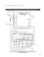
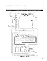
High Voltage Relay Connections
Eight (8) high voltage relays are located in the high voltage
compartment of the System Control Center. One relay (Relay
#1) is dedicated to controlling the filter pump. The remaining
seven relays are general purpose and can be assigned
as required.
The high voltage relays are of the double pole type. They
make and break each leg of a 240 VAC circuit.
240V-rated Equipment: Wire the line power to the two
line terminals of the relay and the equipment to the two
adjacent load terminals.
120V-rated Equipment: Wire the power to a line
terminal and the equipment to an adjacent
load terminal.
Note: Neutral can be broken with the relay if desired
by using the empty line and load terminals on the relay.
Connecting High Voltage Components to the System Control Center
Contact Ratings Not to Exceed 30 Amps
RELAY 8
RELAY 7
RELAY 6
RELAY 5
RELAY 4
RELAY 3
RELAY 2
RELAY 1
FILL VALVE
VALVE 6
VALVE 5
VALVE 4
VALVE 3
VALVE 2
VALVE 1
1
ON
OFF
ON
OFF
240 VAC
Load
ON
OFF
120 VAC
Load
Fig. 17 240V Rated Equipment Connections
Fig. 18 120V Rated Equipment Connections
Line 1
Line 2
Load to
Device
240 VAC
Line
Neutral Bar
Load to
Device
120 VAC
Fig. 16 High Voltage Relay Wiring: 120V & 240V
GENERAL REQUIREMENTS FOR HIGH VOLTAGE EQUIPMENT WIRING
Содержание Poolux
Страница 1: ...1 Installation and Con guration Manual...


