PV4-118310
PAGE 19
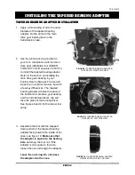
FIGURE 21 |
CHECKING AXIAL END PLAY IN THE
MAIN DRIVE GEAR TAPERED ROLLER BEARING
INSTALLING THE MAIN DRIVE GEAR
6. Do not remove the installation tool yet;
leave everything tight. Measure the
amount of end play in the main drive gear
assembly
using a dial indicator with .0005”
increments as shown in figure 21.
Total
axial end play (pulling / pushing on the
gear) must be between .0005” and
.002
”.
It is extremely important that your
bearing end play is within this range, as
anything too tight or too loose may lead to
transmission failure.
Measuring end play is tricky. The end play
measurement can easily be skewed if
radial or rotational forces are applied, so
try to keep all movement in the axial
direction (parallel to the mainshaft). A
correctly set up tapered roller bearing
should be very tight. When you think your
measurement is between .0005” – .002”,
try spinning the main drive gear. If it spins
freely with no drag and no excessive
noise, setup is complete and you may
proceed to the next step.
7. Remove the tooling used to install the main drive gear along with pulley spacer if you had
to use it. If necessary, reinstall the O-ring (OR568M52) that you removed from the pulley
spacer in step 3.
IF YOUR SETUP IS TOO TIGHT (
UNDER .0005”
), REMOVE THE MAIN DRIVE
GEAR FROM THE CASE USING THE PROPER TOOLING. REMOVE THE O-RING
FROM THE ‘SNOUT’ OF
THE MAIN DRIVE GEAR FOLLOWED BY THE .
104”
(GREEN) SPACER. INSTALL THE
.106” (BLUE) SPACER,
REPLACE THE O-RING,
AND GO BACK TO STEP 4.
IF YOUR SETUP IS TOO LOOSE (OVER .002
”
), REMOVE THE MAIN DRIVE GEAR
FROM THE CASE USING THE PROPER TOOLING. REMOVE THE O-RING FROM
THE ‘SNOUT’ OF THE M
AIN DRIVE GEAR FOLLOWED BY THE .
104” (GREEN)
SPACER. INSTALL THE
.102” (WHITE) SPACER
, REPLACE THE O-RING, AND
GO BACK TO STEP 4.
Watch
Class #4
on the BAKER
Drivetrain YouTube channel for
a video tutorial on setting up
end play in the main drive gear
bearing.
Содержание GRUDGEBOX
Страница 1: ...PV4 118310...
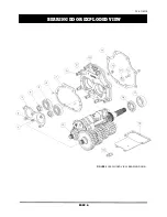
Страница 8: ...PV4 118310 PAGE 6 BEARING DOOR EXPLODED VIEW FIGURE 3 EXPLODED VIEW BEARING DOOR...
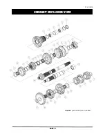
Страница 10: ...PV4 118310 PAGE 8 GEARSET EXPLODED VIEW FIGURE 4 EXPLODED VIEW GEARSET...
Страница 26: ...PV4 118310 PAGE 24 WIRING DIAGRAM FOR IGNITION KILL SHIFT DRUMS...
Страница 29: ...PV4 118310 PAGE 27 DATE ODOMETER WORK PERFORMED SERVICED BY GENERAL MAINTENANCE LOG...
Страница 30: ......

