33
WIRING HARNESS ROUTING
Service Support - M/C
Service Station Manual
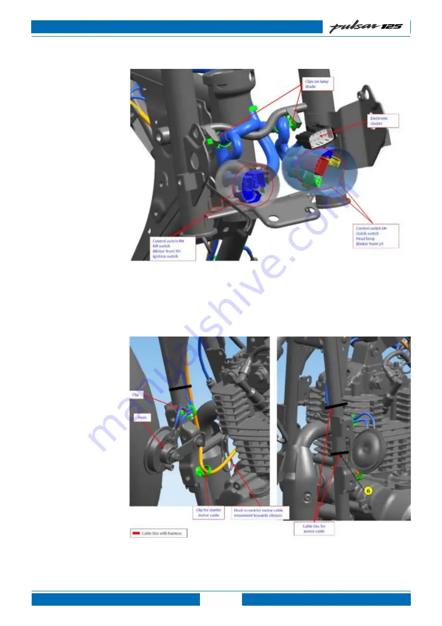
• Route the wiring harness as shown in photograph
Страница 1: ... as existing Pulsar 125 Drum Drum Split seat 00DH38ZZ Same as existing Supplementary Service Station Manual Pulsar 125 BS VI Specification Information Technical Specifications Preventive Maintenance Chart PDI Check Sheet Fuel Tank Cap Speedometer Related Information Side Stand Switch Interlocking Part Identification Wiring Harness Routing Circuit Diagram ...
Страница 2: ... open the flap Insert the key in the lock and turn it clockwise and lift fuel tank cap To lock the Fuel Tank Cap insert the keyin the lock and turn it clockwise and press fuel tank cap Click sound ensures cap is fully locked Precaution Dont attach metallic Key chain as it may damage paint of petrol tank Fuel Tank Cap InstructionsforCustomers Donot REVengineinstandstillcondition Don tuseadulterated...
Страница 3: ...Reset Button Both trip meters can be r e s e t t o zero by pressing the button 9 Trip Meter The Trip meter shows the distance traveled since it was last reset to zero 10 Battery Indicator It shows battery needs charging 11 Hi Beam Indicator It glows when Headlight is ON Hi beam is selected with engine running 12 Neutral Indicator It glows when transmission is in Neutral Ignition switch ON and kill...
Страница 4: ...ouplers 12 Pin coupler 2 pin coupler Light control module 6 pin coupler 2 pin coupler Speedometer branch with single coupler 12 Pin coupler DC Flasher 2 pin coupler Part Name WIRING HARNESS 4 Service Support M C Service Station Manual Part Number Ds201025 Description With Light control module Jl402004 With Flasher Photograph Part Name DC Flasher Light Control Module Model Pulsar 125 00DH32ZZ Pulsa...
Страница 5: ...umber Refer SPC Refer SPC Description NA With tank flaps Part Name Tank Flap 5 Service Support M C Service Station Manual For Pulsar 125 Drum Drum Single seat 00DH36ZZ Same as existing NOTE For part numbers always refer spare parts catalogue available on e ssm Cable Guide Nail Cable guide Shown by pink color Part Number DH201093 JH401413 Description 2 Pin coupler 3 Pin coupler Part Name Switch Sid...
Страница 6: ... Speedometer branch with two couplers 12 Pin coupler 2 pin coupler Side stand switch 2 pin coupler Speedometer branch with single coupler 12 Pin coupler Side stand switch 3 pin coupler Part Name Wiring Harness 6 Service Support M C Service Station Manual Part Number Intake DK102021 Exhaust DK102022 Description NA Intake DK101748 Exhaust DK101751 Design is different than Pulsar 125 00DH36ZZ Existin...
Страница 7: ...oved using 3 mm allen key This screw set Socket is Locking shaft Rocker arm as shown in Photograph Part Number Refer SPC Description Without holes for screw set socket fitment Refer SPC With holes for screw set socket fitment Photograph Part Name Cover Cylinder Head Sub part of Kit Cover Head Cylinder Head Model Pulsar 125 00DH36ZZ Existing Pulsar 125 00DH36ZZ New ...
Страница 8: ...w Cam Sprocket Crankshaft assembly Cam chain Part Number PD511256 Description NA Identification With punch marks DH102546 Cam lobe design is different than Pulsar 125 00DH36ZZ Existing Identification Without punch marks Photograph Part Name Camshaft Assembly Model Part Description LGB Part number Pulsar 125 Silent Timing Chain DH103758 Cam shaft sprocket PF511258 Crank shaft Assembly DH102565 For ...
Страница 9: ...del Pulsar 125 00DH36ZZ Existing Pulsar 125 00DH36ZZ New Part Number DH102528 DH103809 DH102528 Description For DH103809 Catalytic converter cell density more as compared to DH102528 After consumption of DH102528 DH103809 will be implemented Part Name Assembly Silencer ...
Страница 10: ...coupler 3 Pin coupler Part Name Switch Side Stand Pulsar 125 Disc Drum Split seat 00DH34ZZ Same as existing NOTE For part numbers always refer spare parts catalogue available on e ssm Part Number DH201168 DH201173 Description Speedometer branch with two couplers 12 Pin coupler 2 pin coupler Light control module 6 pin coupler 2 pin coupler Side stand switch 2 pin coupler Speedometer branch with sin...
Страница 11: ...upport M C Service Station Manual Part Number DH161825 Description NA DH161719 Design is different than Pulsar 125 00DH34ZZ Existing Photograph Part Name Holder Step Rider LH Model Pulsar 125 00DH34ZZ Existing Pulsar 125 00DH34ZZ New ...
Страница 12: ...coupler 3 Pin coupler Part Name Switch Side Stand Pulsar 125 Drum Drum Split seat 00DH38ZZ Same as existing NOTE For part numbers always refer spare parts catalogue available on E SSM Part Number DH201180 DH201224 Description Speedometer branch with two couplers 12 Pin coupler 2 pin coupler Light control module 6 pin coupler 2 pin coupler Side stand switch 2 pin coupler Speedometer branch with sin...
Страница 13: ...ule DH161719 Design is different than Pulsar 125 00DH34ZZ Existing Photograph Part Name Holder Step Rider LH Model Pulsar 125 00DH38ZZ Existing Pulsar 125 00DH38ZZ New Part Number DH161752 Description NA DH161680 Design is different than Pulsar 125 00DH38ZZ Existing Photograph Part Name Bracket Assembly Number Plate Front ...
Страница 14: ...ll Variants Pulsar 125 New All Variants COMMON FOR Pulsar 125 Disc Drum Single seat 00DH40ZZ Pulsar 125 Drum Drum Single seat 00DH36ZZ Same as existing Pulsar 125 Disc Drum Split seat 00DH34ZZ Same as existing Pulsar 125 Drum Drum Split seat 00DH38ZZ Same as existing NOTE For part numbers always refer spare parts catalogue available on e ssm Part Number JF403000 Description NA NA With Relay Interl...
Страница 15: ...upport M C Service Station Manual Model Pulsar 125 Existing All variants Pulsar 125 New All variants Part Number Refer SPC Refer SPC Description NA Software is different than Pulsar 125 Existing All variants Part Name ECU EMS Assembly ...
Страница 16: ...WIRING HARNESS ROUTING Route the wiring harness as shown in photograph 16 Service Support M C Service Station Manual Pulsar 125 Disc Drum Single seat DH40 ...
Страница 17: ... Route the wiring harness as shown in photograph Route the wiring harness as shown in photograph 17 WIRING HARNESS ROUTING Service Support M C Service Station Manual ...
Страница 18: ... Route the wiring harness as shown in photograph Route the wiring harness as shown in photograph 18 WIRING HARNESS ROUTING Service Support M C Service Station Manual ...
Страница 19: ... Route the wiring harness as shown in photograph Route the wiring harness as shown in photograph 19 WIRING HARNESS ROUTING Service Support M C Service Station Manual ...
Страница 20: ... Route the wiring harness as shown in photograph Route the wiring harness as shown in photograph 20 WIRING HARNESS ROUTING Service Support M C Service Station Manual ...
Страница 21: ... Route the wiring harness as shown in photograph Route the wiring harness as shown in photograph 21 WIRING HARNESS ROUTING Service Support M C Service Station Manual ...
Страница 22: ... Route the wiring harness as shown in photograph 22 WIRING HARNESS ROUTING Service Support M C Service Station Manual ...
Страница 23: ... Route the wiring harness as shown in photograph 23 WIRING HARNESS ROUTING Pulsar 125 Disc Drum Split seat DH34 ...
Страница 24: ... Route the wiring harness as shown in photograph Route the wiring harness as shown in photograph 24 WIRING HARNESS ROUTING Service Support M C Service Station Manual ...
Страница 25: ... Route the wiring harness as shown in photograph Route the wiring harness as shown in photograph 25 WIRING HARNESS ROUTING Service Support M C Service Station Manual ...
Страница 26: ... Route the wiring harness as shown in photograph Route the wiring harness as shown in photograph 26 WIRING HARNESS ROUTING Service Support M C Service Station Manual ...
Страница 27: ... Route the wiring harness as shown in photograph Route the wiring harness as shown in photograph 27 WIRING HARNESS ROUTING Service Support M C Service Station Manual ...
Страница 28: ... Route the wiring harness as shown in photograph Route the wiring harness as shown in photograph 28 WIRING HARNESS ROUTING Service Support M C Service Station Manual ...
Страница 29: ... Route the wiring harness as shown in photograph 29 WIRING HARNESS ROUTING Service Support M C Service Station Manual ...
Страница 30: ... Route the wiring harness as shown in photograph 30 WIRING HARNESS ROUTING Service Support M C Service Station Manual Pulsar 125 Drum Drum Single seat DH36 ...
Страница 31: ...31 WIRING HARNESS ROUTING Service Support M C Service Station Manual Route the wiring harness as shown in photograph Route the wiring harness as shown in photograph ...
Страница 32: ...32 WIRING HARNESS ROUTING Service Support M C Service Station Manual Route the wiring harness as shown in photograph Route the wiring harness as shown in photograph ...
Страница 33: ...33 WIRING HARNESS ROUTING Service Support M C Service Station Manual Route the wiring harness as shown in photograph Route the wiring harness as shown in photograph ...
Страница 34: ...34 WIRING HARNESS ROUTING Service Support M C Service Station Manual Route the wiring harness as shown in photograph Route the wiring harness as shown in photograph ...
Страница 35: ... Route the wiring harness as shown in photograph Route the wiring harness as shown in photograph 35 WIRING HARNESS ROUTING Service Support M C Service Station Manual ...
Страница 36: ... Route the wiring harness as shown in photograph 36 WIRING HARNESS ROUTING Service Support M C Service Station Manual ...
Страница 37: ... Route the wiring harness as shown in photograph 37 WIRING HARNESS ROUTING Service Support M C Service Station Manual Pulsar 125 Drum Drum Split seat DH38 ...
Страница 38: ... Route the wiring harness as shown in photograph Route the wiring harness as shown in photograph 39 WIRING HARNESS ROUTING Service Support M C Service Station Manual ...
Страница 39: ... Route the wiring harness as shown in photograph Route the wiring harness as shown in photograph 40 WIRING HARNESS ROUTING Service Support M C Service Station Manual ...
Страница 40: ... Route the wiring harness as shown in photograph Route the wiring harness as shown in photograph 41 WIRING HARNESS ROUTING Service Support M C Service Station Manual ...
Страница 41: ... Route the wiring harness as shown in photograph Route the wiring harness as shown in photograph 42 WIRING HARNESS ROUTING Service Support M C Service Station Manual ...
Страница 42: ... Route the wiring harness as shown in photograph Route the wiring harness as shown in photograph 43 WIRING HARNESS ROUTING Service Support M C Service Station Manual ...
Страница 43: ... Route the wiring harness as shown in photograph 44 WIRING HARNESS ROUTING Service Support M C Service Station Manual ...
Страница 44: ...IT G 8 LEFT TURN INDICATOR Gr 7 RIGHT TURN INDICATOR 9 N C 11 GROUND 10 N C 12 GROUND 14 N C 13 BACKLIGHT 15 N C Y L 17 CAN LOW 16 CAN HIGH 18 N C 19 N C W 20 BATTERY R G L B Y B Y L W 2 1 4 3 6 5 8 7 9 11 10 12 Br Gr R W Y Gr G G L B Y V W Y L 46 ELECTRIC CIRCUIT DIAGRAM Service Support M C Service Station Manual Speedometer Pin Details ...
Страница 45: ... SWITCH SUPLLY KEP 10 IGNITION HT COIL II 11 V BATTERY 12 XDRG 13 XDRP 14 SIDE STAND SWITCH 15 TPS 16 NEUTRAL SWITCH 17 ULS LAMDA SENSOR 18 CPS VE 19 CPS VE CRANK POSITION SENSOR 20 GROUND B Br B R G V B O Br G L Y L B W Gr R B R W Y B R L P I G Y L G L Y W R B Y 47 ELECTRIC CIRCUIT DIAGRAM Service Support M C Service Station Manual Control Unit Pin Details ...
Страница 46: ...D 2 11 20 10A Br F2 F1 W 15A Br L R W B Y W Br 1 9 5 1 2 2 1 1 2 3 4 CONTROL SWITCH RH Gr R ON OFF KILL SWITCH Br L 2 1 Br L CAN INTERFACE Y L B Y G L Br 1 3 6 2 Gr R FRAME EARTH B Y CONTROL UNIT 6 CAN HIGH 7 CAN LOW 11 V BATTERY 20 GROUND G L Y L W B Y 9 KILL SWITCH SUPLLY KEP Gr R Y L 17 CAN LOW 16 CAN HIGH G L G L Y L 12 7 B OFF ON FUSE BOX ELECTRIC CIRCUIT DIAGRAM 48 Service Support M C Servic...
Страница 47: ... L B Y G L Br 1 3 6 2 3 1 2 SIDE STAND SWITCH Pi Pi Y B R L Pi L O Br R Y INTERMEDIATE RELAY 5 CONTROL UNIT 3 INTERMEDIATE RELAY 6 CAN HIGH 7 CAN LOW 11 V BATTERY 12 XDRG 13 XDRP 14 SIDE STAND SWITCH 16 NEUTRAL SWITCH 20 GROUND R G G L Y L W Y B R L Pi L G B Y 9 KILL SWITCH SUPLLY KEP Gr R 7 G L Br 2 IGNITION SUPLY Gr R 4 KILL SW SUPPLY 11 GROUND Y L 17 CAN LOW 16 CAN HIGH W 20 BATTERY G L B Y 1 3...
Страница 48: ...H Gr R ON OFF KILL SWITCH Br L 2 1 Gr R Br L Br 2 11 Y L 17 16 W 20 G L 1 8 10 12 Br B Y W Y L 11 CONTROL UNIT 1 IGNITION HT COIL I 5 AUTO CHOKE SOLENOID 6 CAN HIGH 7 CAN LOW 8 ENGINE TEMP SENSOR 9 KILL SWITCH SUPLLY KEP 10 IGNITION HT COIL II 12 XDRG 13 XDRP B O Br G L Y L B W Gr R B R Y B R L 15 TPS 17 ULS LAMDA SENSOR 19 CPS VE CRANK POSITION SENSOR 20 GROUND G Y L Y B Y W R G L 4 3 Gr R Gr R 1...
Страница 49: ...N OFF KILL SWITCH Br L 2 1 Gr R Br L Br 2 11 W 20 1 8 10 Br B Y W 4 W Y 4 5 3 Gr R Gr R 10A F2 FUSE BOX OFF ON B Br W SPEEDOMETER IGNITION SUPLY GROUND BATTERY KILL SWITCH SUPPLY FUEL UNIT W Y 2 1 B Y B Y W Y W Y FUEL LEVEL GAUGE 51 ELECTRIC CIRCUIT DIAGRAM Service Support M C Service Station Manual ...
Страница 50: ...N INTERFACE Y L B Y G L Br 1 3 6 2 CONTROL UNIT 6 CAN HIGH 7 CAN LOW 11 V BATTERY 20 GROUND G L Y L W B Y 9 KILL SWITCH SUPLLY KEP Gr R 7 G L Br 2 IGNITION SUPLY Gr R 4 KILL SW SUPPLY 11 GROUND Y L 17 CAN LOW 16 CAN HIGH W 20 BATTERY G L B Y 1 3 8 10 12 Br Gr R B Y W Y L SPEEDOMETER Gr R B OFF ON 52 ELECTRIC CIRCUIT DIAGRAM Service Support M C Service Station Manual ...
Страница 51: ... B O Br B W FRAME EARTH B Y AIR SOLENOID CAN_HIGH 2 6 CAN_LOW 7 KILL SWITCH SUPLLY KEP 9 V BATTERY 11 GROUND 20 Br B G L Y L Gr R W B Y 1 2 2 1 CONTROL SWITCH RH Gr R ON OFF KILL SWITCH Br L 2 1 Gr R Br L Y L G L 7 12 G L Y L 17 CAN LOW 16 CAN HIGH FUSE BOX B OFF ON Br W SPEEDOMETER 53 ELECTRIC CIRCUIT DIAGRAM Service Support M C Service Station Manual ...
Страница 52: ... 3 6 2 FRAME EARTH CONTROL UNIT CAN_HIGH 6 CAN_LOW 7 9 KILL SWITCH SUPLLY KEP 11 G L Y L Gr R W GROUND 20 B Y B Y 1 2 2 1 3 V BATTERY 1 8 7 10 12 Br G L B Y W Y L R Br 2 IGNITION SUPLY R W 1 SPEED SENSOR SUPPLY 6 SPEED SENSOR INPUT 11 GROUND 12 GROUND Y L CAN LOW 16 CAN HIGH W 20 BATTERY G L B Y B Y L W 17 Br W OFF ON B 10A F2 FUSE BOX SPEEDOMETER 54 ELECTRIC CIRCUIT DIAGRAM Service Support M C Se...
Страница 53: ...ITION SWITCH Br L W Br W 10A Br F2 F1 W 15A Br L R 1 2 1 2 4 3 2 3 L L B Y B Y FRONT BRAKE SWITCH Br Br L L L L Br Br REAR BRAKE SWITCH TAIL LAMP B OFF ON FUSE BOX 55 ELECTRIC CIRCUIT DIAGRAM Service Support M C Service Station Manual ...
Страница 54: ...F KILL SWITCH Br L 2 1 HEADLAMP RELAY 4 V BATTERY 11 GROUND 20 Y B W B Y KILL SWITCH SUPLLY KEP 9 Gr R B G Br W 2 1 B G Br W LED 2 1 5 1 LED CONTROL INPUT OUTPUT Gr R Br L B Y V Br W B G Br W B G B Y V B Y R R B R Y B Y 1 Br R B Br Gr R R B W R B Y 2 3 8 9 10 Gr R B Y V W TAIL LAMP 1 3 B Y V R 1 2 B Y R V B Y B Y NUMBER PLATE LAMP Br W OFF ON B FUSE BOX SPEEDOMETER 2 IGNITION SUPLY 4 KILL SWITCH S...
Страница 55: ...INDICATOR SELECTOR SWITCH 2 1 B Y Gr Gr B Y 2 1 B Y G G B Y Gr B Y G B Y G 8 LEFT TURN INDICATOR Gr 7 RIGHT TURN INDICATOR 6 5 Gr G DC FLASHER 2 1 O Br O Br BATTERY R Br F1 W 15A Br L R 10A F2 B FUSE BOX SPEEDOMETER FRONT INDICATOR RH FRONT INDICATOR LH 1 2 B Y Gr REAR INDICATOR RH 2 1 B Y G REAR INDICATOR LH 57 ELECTRIC CIRCUIT DIAGRAM Service Support M C Service Station Manual ...