17
17
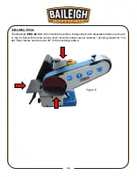
Changing the Disc
1. Shut off the machine, making sure the driving
wheel has completely stopped.
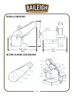
2. Remove the working table assembly (
11
).
3. Peel off the used disc which utilizes a hook and
loop method of attachment as shown in (fig. 5).
4. Place a new disc onto the back plate, making
sure to keep it centered. Press to ensure good
contact.
5. Replace the working table assembly (
11
).
Angular Adjustment for Body Frame
1. Shut off the machine, making sure the driving
wheel has completely stopped.
2. Remove the working table assembly (11).
3. Peel off the sanding / grinding disc.
4. There are (four) socket head cap screws that
need to be loosened in order for the body frame
to pivot. They can be accessed through the two
holes in the back plate. (Note: You may have to
provide clearance holes through the loop material
for inserting the allen wrench.
5. After setting the desired angle, tighten the (four) hex cap screws.
6. Replace the sanding / grinding disc and the working table assembly (11).
figure 6
figure 7
Содержание DBG-62
Страница 13: ...11 11 OVERALL DIMENSIONS GETTING TO KNOW YOUR MACHINE 19 68 max 500 16 14 410 20 47 max 520...
Страница 22: ...20 20 PARTS IDENTIFICATION DRAWING...
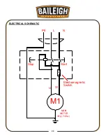
Страница 25: ...23 23 ELECTRICAL SCHEMATIC M1 L N PE MAIN MOTOR U W 1Hp 74Kw Stop Start Electromagnetic Switch...
Страница 27: ...25 25...

