


Page 12/24
Operating Instructions
BA 7020
Technical specifications subject to change without notice
Copyright according to ISO 16016
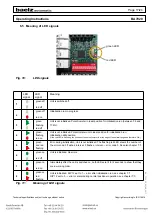
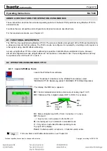
6. DETAILED INSTRUCTIONS
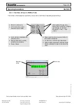
6.1 Functions in standard mode:
These operation instructions concern the standard mode. The DIP switches are used to define the most commonly
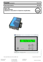
required configurations. In Modbus mode, the user can carry out additional advanced settings. The advanced
settings are explained in a separate set of operating instructions: "Baelz 7020 Digital Positioner - Operating
Instructions for Modbus Mode"
In standard mode, the following functions are predefined:
●
The setpoint actual value is supplied to both analogue outputs (both can be connected).
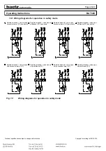
● DIP switches 7, 8 and 9 are used to define the function of the positioner in standard mode. In standard
mode, the positioner is set to heat. In standard mode, cooling can be selected by setting all three DIP
switches, 7, 8 and 9, to position 1. Combination with split range or the 11-point characteristic is, however,
not possible.
●
Values for valve stroke time and switching hysteresis are determined during the initialisation run. These
values are used in standard mode.
●
Sensor failure at analogue input 1 and analogue input 2 (AI1 and AI2) as well as alarm 3 and alarm 4 are
part of the "collective alarm" (only accessible with Modbus RTU).
●
In standard mode there are no minimum or maximum limits for the set values at the analogue inputs and
analogue outputs. Values from 0% to 100% are possible.
●
In case of sensor failure at analogue input AI1 or AI2, the ventil closes.
●
In case of a signal to the digital input, e.g. from an antifreeze thermostat, the ventil opens.
●
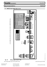
All DIP switches are enabled and kann be operated according to Fig. Fig. 6 page 13.


