background image

88

9

The preferred method of installation is by means of a saddle with 1” NPT out

-

let. On steel pipelines a weld-on type fitting may be substituted.  

1.  Attach the saddle to a section of pipe that has at least 10 diameters of 

straight pipe ahead and five diameters of straight pipe behind the saddle. 

2.  Remove the sensor assembly from the mounting/isolation valve by 

loosening the hex cap over the stem collar and the cover to the mounting/

isolation valve and detaching the assembly.  Set aside taking care not to 

damage impeller/shaft assembly.

3.  Attach the pipe thread end of the valve to the saddle using a pipe joint 

compound and tighten the joint. 

Do not apply sealing compound to the top 

thread of the valve.  It is sealed with an o-ring.

4.  Attach the tapping adapter, Data Industrial part number A-1027 to the top 

of the valve.  

5.  Any pipe tapping machine with a 1” pipe thread connection may be used.  

Use a cutter appropriate for the pipe material being tapped. 

6.  Attach the tapping machine to 

the tapping adapter. Ensure 

that all connections and seals 

are tight. 

7.  Slowly open the valve by 

rotating the handle 90° and lower the cutter past the valve ball to 

the pipe.  Drill the 1” nominal hole according to the manufacturer’s 

instructions. Withdraw the cutter past the valve ball, close the valve 

and remove the tapping tool.

8.  Remove the Data Industrial tapping adapter from the top of the 

valve.

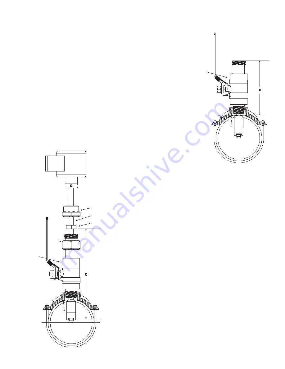
9.  The sensor rotor assembly is to be located a fixed distance from the 

center of the pipe.  To position the impeller at this depth, a reference 

measurement for the pipe size and schedule is used.  Look up the 

pipe size and schedule number in 

Table A 

and note the reference 

number.   Next, measure from the outside wall of the pipe to the top 

of the ball valve “B” in Figure 8.  Add this number to the reference 

measurement.


The resulting number is the distance from the recess of the sensor 

tip to the bottom of the stem collar “C” in Figure 9. Insert the metal 

tab of a tape measure into the recess of the flow sensor tip. Extend 

the tape up the stem and mark the shaft with a pencil.  Slide the 

collar along the shaft until its bottom surface is at the mark on the 

stem. Tighten the cap screw on the collar. When the sensor is 

reassembled, this will set the insertion depth of the sensor. 

Pipe Saddle

(ref.)

Gasket

(ref)

Ball Valve

Stem Collar

Stem

Hex Cap

Cover

Pipe Saddle

(ref.)

Gasket

(ref)

Ball Valve

Содержание SDI Series

Страница 1: ...Installation Operation Manual BadgerMeter Inc PN 72034 1 09 Rev B8 SDI Series Insert Style Flow Sensors ...

Страница 2: ...2 2 This page intentionally left blank ...

Страница 3: ...itting is preferred over a service tee because it causes fewer disturbances to the flow Models Available Direct insert sensor models are installed in piping configurations that are not in service or under pressure Hot tap insert sensor models feature isolation valves and mount ing hardware to install or remove the sensor from a pipeline that would be difficult to shut down or drain In a true hot t...

Страница 4: ...e output choice pipe size output scale and direction of flow by the user are also accomplished by using a PC with Data Industrial software and A 301 connection cable This option SDI Series Hot Tap Ordering Matrix SDI 0 H1 N 0 0 0 2 0 0 Material Stainless Steel PPS Tip 0 Stainless Steel PEEK Tip 2 Type Hot Tap for Pipe 1 1 2 thru 10 H1 Hot Tap for Pipe 12 thru 36 H2 Hot Tap for Pipe 36 and UP H3 El...

Страница 5: ...esigned to operate reliably under adverse conditions but the following recommendations should be followed to ensure maximum system accuracy 1 Choose a location along the pipe where there is straight pipe for a distance of 10 pipe diameters upstream and 5 pipe diameters downstream of the sensor Pipe bends valves other fittings pipe enlargements and reductions or anything else that would cause a flo...

Страница 6: ...tion of flow sensors into piping systems that are not under pressure at the time of installation If the line must be tapped under pressure a hot tap style sensor must be used See following section for hot tap installation instructions The insertion depth and alignment of the sensor are critical to the accuracy of the flow measurement The impeller must be at the same location in the pipe as it was ...

Страница 7: ...ber to the reference mea surement The resulting number C in Figure 4 is the distance from the recess of the sensor tip to the bottom of the stem collar Insert the metal tab of a tape measure into the recess of the flow sensor tip Extend the tape up the stem and mark the shaft with a pencil Slide the collar along the shaft until its bottom surface is at the mark on the stem Tighten the cap screw on...

Страница 8: ...lengths Longer stems are intended for use in larger diameter pipes and shorter stems for use in smaller pipelines However stem length has no affect on the operation of the sensor provided that the impeller is positioned correctly in the center of the pipe Stem length H1 is intended for use in nominal pipe diameters from 1 1 2 to 10 H2 is for nominal pipe diameters from 12 to 36 and stem length H3 ...

Страница 9: ... rotating the handle 90 and lower the cutter past the valve ball to the pipe Drill the 1 nominal hole according to the manufacturer s instructions Withdraw the cutter past the valve ball close the valve and remove the tapping tool 8 Remove the Data Industrial tapping adapter from the top of the valve 9 The sensor rotor assembly is to be located a fixed distance from the center of the pipe To posit...

Страница 10: ...ctronics housing with a slight twisting motion until the stem collar meets the cover The force required to push the sensor into the pipeline is approximately 20 of the line pressure Be aware of the close spacing between the diameter of the flow sensor the bore of the ball valve and the hole in the pipe If the sensor stops or catches before the stem collar meets the cover apply a gentle rocking twi...

Страница 11: ...nd or Power Supply Common This provides maximum power and signal EMI protection ANALOG OUTPUT WIRED AS CURRENT SINKING Attach SDI 2 Loop to the Analog input terminal of device receiving this 4 20mA signal Attach SDI 3 Loop to 24VDC terminal of device receiving the 4 20mA Signal ANALOG OUTPUT WIRED AS CURRENT SOURCING WITH SEPA RATE 24VDC POWER SUPPLY Attach SDI 2 Loop to Analog input terminal of d...

Страница 12: ...rminal with 24VDC Supply Attach SDI 2 Loop to Analog Input Common Sometimes labeled Loop ANALOG OUTPUT WIRED AS CURRENT SOURCING WITH SEPARATE 24VDC POWER SUPPLY Attach SDI 6 Loop to Analog input terminal of device receiving this 4 20mA signal Sometimes labeled Loop Attach SDI 7 Loop to 24VDC Supply terminal Attach 24VDC Supply terminal to the Analog Input Common Sometimes labeled Loop Bi Directio...

Страница 13: ... properly align the tab on the plug and socket to maintain polarity Connect the DB9 connector of the Data Industrial A 301 communications cable to the PC com port of a PC that has the SDI soft ware installed 3 Connect the Series SDI Flow Sensor to a power supply 4 Open the interface software and select the appropriate COM PORT as shown in the dialog box below 5 Open the Parameters Screen as shown ...

Страница 14: ...pe size from the pull down menu if the pipe size is not present then custom must be selected or check for an updated pipe dat table on the Data Industrial web site See Note 1 Step 4 Note 2 If custom was selected in step 3 then click the custom button and see Step 5 Enter 4mA flow rate This is normally zero Step 6 Enter 20mA flow rate Step 7 Step 8 For models with LCD Display Option select the desi...

Страница 15: ...pull down menu if the pipe size is not present then select custom or check for an updated pipe dat table on the Data Industrial web site See Note 1 Step 4 Note 2 If custom was selected in step 3 then click the custom button and see Step 5 Enter the number of units per pulse and select the pulse width required Step 7 Press Send to transmit calibration data to the SDI Sensor Press to retrieve calibr...

Страница 16: ...he pull down menu if the pipe size is not present then select custom or check for an updated pipe dat table on the Data Industrial web site See Note 1 Step 4 Note 2 If custom was selected in step 3 then click the custom button and see Step 5 Enter 4mA flow rate This is normally zero Step 6 Enter 20mA flow rate Step 8 Select Active Direction Step 9 If the Flow direction label requires changing see ...

Страница 17: ...esent then select custom or check for an updated pipe dat table on the Data Industrial web site See Note 1 Step 4 Note 2 If custom was selected in step 3 then click the custom button and see Step 5 Step 6 Select the pulse output type that is required If raw pulse is selected skip Step 8 Select Active Direction Step 9 If the Flow direction label requires changing see Note 3 Step 10 Press Send to tr...

Страница 18: ...ect the PC to the SDI with the Data Industrial A 303 communications cable Plug in the the RJ11 plug on the A 303 cable to the RJ11 socket on Battry Powered SDI Connect the DB9 connector of the A 303 cable to the PC com port to a PC that has the SDI software installed 3 Open the interface software and select the appropriate COM PORT as shown in the dialog box below 4 Open the Parameters Screen as s...

Страница 19: ... 1 Press to retrieve calibration data from SDI Press to reset all parameters back to factory defaults Send must be pressed to send this data to the SDI Step 8 See Note 2 Press to exit parameters screen and to go back to the main screen Note 1 After the send button is pressed the unit could take up to one and a half minutes to program the Battery Powered SDI The illustration below shows the program...

Страница 20: ...1 59 2 5 8 134 1 59 2 5 8 258 1 63 2 21 32 258 1 63 2 21 32 375 1 44 2 11 16 6 6 625 Wall Insertion Depth Customer Ref 134 1 91 2 29 32 134 1 91 2 29 32 280 1 82 2 31 32 280 1 82 2 31 32 432 1 73 3 1 32 316 1 83 3 1 32 8 8 625 Wall Insertion Depth Customer Ref 148 2 50 3 17 32 148 2 50 3 17 32 322 2 39 3 19 32 322 2 39 3 19 32 500 2 29 3 21 32 410 2 40 3 11 16 10 10 750 Wall Insertion Depth Custom...

Страница 21: ...h Customer Ref 312 4 41 5 19 32 312 4 41 5 19 32 375 4 39 5 5 8 For sizes above 30 consult factory Pipe O D Schedule or pipe O D I D or pipe O D wall thickness is required Copper Tube Type Size O D K L M DWV 1 1 2 1 625 Wall Insertion Depth Customer Ref 072 48 1 7 16 060 49 1 7 16 049 50 1 7 16 042 51 1 7 16 2 2 125 Wall Insertion Depth Customer Ref 083 72 1 11 16 070 73 1 11 16 058 74 1 11 16 042...

Страница 22: ...C AWWA C900 Size O D CL100 4 4 800 Wall Insertion Depth Customer Ref 192 1 77 2 27 32 6 6 900 Wall Insertion Depth Customer Ref 276 1 90 3 1 16 8 9 050 Wall Insertion Depth Customer Ref 362 2 50 3 23 32 10 11 100 Wall Insertion Depth Customer Ref 444 3 06 4 3 8 12 13 200 Wall Insertion Depth Customer Ref 528 3 64 5 1 16 For other types of pipe not listed above consult factory Pipe O D Schedule or ...

Страница 23: ... 093849 6 6 625 K Offset 5 144059 3 295640 5 144059 3 295640 4 642584 3 295640 4 642584 3 295640 4 237085 2 093849 8 8 625 K Offset 8 730561 2 793790 8 730561 2 793790 10 10 750 K Offset 13 737621 2 937799 13 737621 2 937799 12 476283 2 937799 12 12 750 K Offset 19 830912 2 768877 20 041272 2 768877 17 796906 2 937799 14 14 000 K Offset 24 238528 2 768877 24 702144 2 768877 16 16 000 K Offset 31 7...

Страница 24: ... 295640 Ductile Iron Because of the variety of iron pipe classes sizes and wall thicknesses consult factory for customer reference number Pipe O D Schedule or pipe O D I D or pipe O D wall thickness is required PVC Municipal C900 Schedules Size O D 100 4 4 800 K Offset 6 6 900 K Offset 8 9 050 K Offset 10 11 100 K Offset 12 13 200 K Offset For other types of pipe not listed above consult factory P...

Страница 25: ...rovided Programming all programmable models utilize Data Industrial A 301 connector cable and SDI Series software Display optional 8 character 3 8 LCD STN Super twisted Nematic display annunciators for rate total input output flow direction for Bi directional models Accessories ASDI Programming Kit A1027 Hot Tap Adapter Nipple raw pulse option 0 Number of wire connections 2 Pulse Units Operating V...

Страница 26: ...26 26 This page intentionally left blank ...

Страница 27: ...27 This page intentionally left blank ...

Страница 28: ...e extent an outstanding contractual obligation exists BadgerMeter Inc Copyright Badger Meter Inc 2009 All rights reserved Viton is a registered trademark of DuPont Dow Elastomers Torlon is a registered trademark of Amoco Performance Products Windows is a registered trademark of Microsoft Corporation Hastelloy is a registered trademark of Haynes Corporation ...

Отзывы: