background image

 
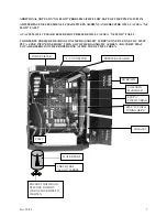
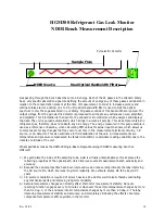
HGM300 Refrigerant Gas Leak Monitor 
Dual Loop 4 to 20 mAdc Scrolling Output


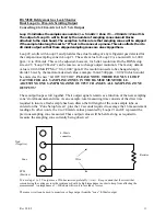
Converting 4 to 20 mAdc to 1 to 5 V dc Output 


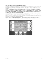
Loop #1 indicates the sample zone number; i.e. 5 mAdc = Zone #1 … 20 mAdc = Zone #16. 

The output of Loop #1 will be fixed by the number of sampling zone solenoid blocks 

attached to the main board. The exception to this rule is that sampling zones will be skipped 
if the sample tube length is set to “0” feet in the zone set up menu. This also affects the 4 to 

20 mAdc output so that these skipped sampling zones are also skipped here. 


Loop #2 scrolls with Loop #1 and provides the actual reading of any refrigerant gas detected for 
the companion sampling zone in Loop #1. The scale value for Loop #2 is a nominal 0 to 1,000 
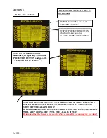
ppm = 4 to 20 mAdc. This can be adjusted, however, for better resolution. On the HGM setup 
screen #2, “Loop #2 Factor” can be reset so as to change output resolution. The factory default 
value is 0.0160 MA/PPM or “0 to 1,000” ppm. If the resolution needs to be changed simply 
divide 16 mA by the maximum desired value; example: 16mA/500 ppm = 0.0320 which would 
be entered as the new “LOOP2 FACTOR”. 

PLEASE NOTE: THERE IS ONLY 1 LOOP 

FACTOR FOR ALL SAMPLING ZONES IN THE HGM300 MONITOR; I.E. 
ADJUSTING ONE SAMPLING ZONE OUTPUT CHANGES ALL SAMPLING ZONE 
OUTPUTS! 

 
These output loops scroll together. Their output signals remain as a function of the next sampling 
zone’s total measurement time. As an example: total measuring time consists of the draw time 
required to insure a fresh sample has been drawn the full length of the zone sample tube, as 
entered on the “Zone Setup Screen”, plus the 12 seconds required to average the 16 measurement 
readings. In other words, the 4 to 20 mAdc values presented by Loops #1 and #2 represent the 
previous sampling zone measured. These output values will be held as long as required to 
measure the sampling zone currently being observed. 


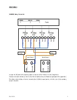
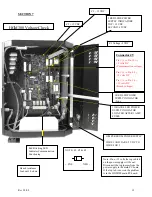
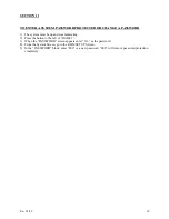
To develop a 1 to 5 V output use a 250ohm resistor, preferably ½ watt.   Keep in mind that the circuit that 

Wire 

PPM 
(Positive) 

4-20mA 
connector 

Gnd 
(Negative) 

Resistor 

Zone 

is monitoring the voltage across the resistance should be high impedance in order to keep from affecting the 
measurement.  An impedance of > 50Kohms will result in less than 1% error. 
 
The same circuit can be used to monitor a voltage output from the “zone” 4-20mA output 


Rev 3/2/09 

11

Содержание HGM300

Страница 1: ...nector SECTION 4 Flow check procedure SECTION 5 Clipping fault adjustment SECTION 6 Dual loop 4 20 mA dc scrolling output SECTION 7 HGM300 voltage check Dual loop 4 20 mA dc scrolling output SECTION 8...

Страница 2: ...pressure check This may be helpful in analyzing problems with the monitor HGM300 Self Test Mode The HGM300 refrigerant monitor has a built in self test mode that will test the following functions To s...

Страница 3: ...ring the 4 20mA test then all lights will go out and both the HGM300 and RDM800 will return to power on green only COMMON RDM800 INDICATIONS Initial start up of the HGM300 RDM800 system TIME OUT ERROR...

Страница 4: ...leak monitor mechanical room placement Sample Inlet Pickup Points Chiller RDM800 Remote Display Module Outside Hallway Machine Room Exhaust Fan Aux Horn Strobe Remote Alarm Sample Inlet Pickup Point...

Страница 5: ...Power Line Neutral Strobe Horn Line Neutral Jumper the Neutral of the auxiliary power connector to the Common on the relay block Connect one end of strobe or horn to the NO of whichever level of alarm...

Страница 6: ...the water trap If they are cracked or broken the monitor may see only 4 zones 1 Pinch off the tubing between the water trap and in line filter Go to the diagnostic screen on the RDM800 Observe the PR...

Страница 7: ...ERVE PRESSURE READINGS ON THE DIAGNOSTIC SCREEN ZONE BY ZONE YOU MUST PUT A ZONE INTO ZONE HOLD THEN GO TO THE DIAGNOSTIC SCREEN AND VERFY THAT YOU ARE OBSERVING THE PROPER ZONE AT THE TOP OF THE SCRE...

Страница 8: ...then go to the tubing between the solenoid assembly and the water trap and pinch it closed 3 If the pressure does not drop to the same level as the first reading the problem is in the water trap 4 If...

Страница 9: ...ALARM LIGHT WILL NOW BE FLASHING PRESS THE BUTTON TO THE RIGHT THE SCREEN NOW SHOWS IN SERVICE QUIT FLASHING TWO TIMES WITHIN THREE SECONDS THE RED LIGHT WILL GO OUT ON THE HGM300 RETURN TO THE SYSTEM...

Страница 10: ...voltage change to appear on the diagnostic screen due to the cycle time of the monitor from zone to zone If the clipping fault remains the reference voltage must be verified and corrected if needed L...

Страница 11: ...320 which would be entered as the new LOOP2 FACTOR PLEASE NOTE THERE IS ONLY 1 LOOP FACTOR FOR ALL SAMPLING ZONES IN THE HGM300 MONITOR I E ADJUSTING ONE SAMPLING ZONE OUTPUT CHANGES ALL SAMPLING ZONE...

Страница 12: ...C SECOND 15VDC Z2 15 VDC 1 RED LED POWER SUPPLY INDICATOR 5vdc NOTE Z1 Z2 Z3 POS NEG 1 ORANGE LED POWER SUPPLY INDICATOR LOCATED AFTER 1 AMP FUSES JUMPER FROM POWER SUPPLY WIRE 1 AND 2 ARE 5 V DC TO W...

Страница 13: ...edged separately To do that PRESS THIS BUTTON and go to the ALARM DETAIL SCREEN STEP 4 PRESS THIS BUTTON TO ACKNOWLEDGE THIS ALARM ANY OTHER ALARMS WILL HAVE TO BE DEALT WITH IN THIS WAY TO SHUT OFF T...

Страница 14: ...may occur over time in the measurement electronic circuitry I R source or I R detector This also eliminates for field calibration of the unit All measurements are temperature and pressure compensated...

Страница 15: ...racy 7 All measurements are pressure and temperature compensated so that there is never a question arising from local weather or altitude issues We always provide the same information regardless of th...

Страница 16: ...GM300 running the HGM300 PC software This may be convenient if HGM300 is remotely located from RDM800 See M1110AY A for procedure using PC software 4 From the RDM800 system menu press the switch that...

Страница 17: ...he reading should be within 10 of the concentration indicated on the reference bottle NOTE The unit may go into a purge cycle during the test process If this happens the PPM reading will drop to appro...

Страница 18: ...dated On version 1 0 software it is necessary to select the HGM Pulldown Menu and then send the setup in order to confirm the changes 5 Select the HGM Pulldown Menu and then choose the get setup item...

Страница 19: ...while observing the first PPM reading 6th line from the sensor data menu This value will stabilize to typically within 5PPM of final reading IF a purge cycle interrupts the process the reading will go...

Страница 20: ...up and communicating 2 Press the button to the left of HGM 1 3 When the PASSWORD screen appears enter 313 as the password 4 From the System Screen go to the RDM SET UP Screen 5 In the PASSWORD block...

Страница 21: ...SS BACHARACH INC 621 Hunt Valley Circle New Kensington PA 15068 WARRANTY HIGHLIGHTS PLEASE REVIEW COMPLETE WARRANTY CONDITIONS PARTS 2 YEARS AFTER SHIPMENT FROM FACTORY UNLESS OTHERWISE NEGOTIATED DRI...

Отзывы: