Bacharach AGM-SZ Скачать руководство пользователя страница 22

Single Zone Gas Monitor 

18 

P/N: 3015-4256 Rev 13 

3.2.  General Operation 

Once the SZ monitor has been installed, set up, and powered ON, the 
monitor will make measurements in the area being sampled for desired 
gas without further operator intervention. The results of those 
measurements are shown on the front panel display. 


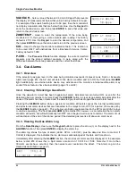
In the example shown above, 

MEASURE

  indicates that the SZ  unit  is actively monitoring  for  refrigerant 

gas, and that currently 45 ppm of R-134A (refrigerant gas) is being detected. This display also indicates 
that a peak measurement of 485 ppm has been made. 

An operator can reset the peak value to zero by pressing the 

ENTER

 button. 

A log of up to 200 previous measurements can be viewed using the 

PPM LOG 

function (page 22). 

If the detected gas level exceeds the preset Leak, Spill, or Evacuate alarm point, then the monitor 
responds by turning ON the front panel 

ALARM

 (red) light and energizing the corresponding alarm relay. 

If the internal audible alarm is turned ON, it too will activate (

AUDALRM

  page  22). Optional external 

alarm devices can be connected to the alarm relays to alert personnel that a Leak, Spill, or Evacuate 
alarm condition has occurred (page  14). Pressing the front panel 

SILENCE 

button will acknowledge an 

alarm and turn OFF all alarm indicators with the exception of the front panel 

ALARM

  light. The alarm 

circuit will reactivate, however, if the alarm condition is not cleared within the time period set by the 

SILENCE 

function (page 22). The ALARM light will turn OFF after the detected gas level goes below the 

lowest alarm point and after the 

SILENCE

 button is pressed. 

If a system fault occurs (see Fault Code list on page  23), the monitor responds by turning ON the front 
panel 

SYSTEM FAULT

 (yellow) light and energizing the fault relay. If the internal audible alarm is turned 

ON, it too will activate (

AUDALRM

 page 22). An optional external alarm device can be connected to the 

fault relay to alert personnel that a system fault has occurred  (page  14). Pressing the front panel 

SILENCE 

button will acknowledge the fault and turn OFF all alarm indicators with the exception of the 

front panel 

SYSTEM FAULT

  light. The alarm circuit will reactivate, however, if the fault condition is not 

cleared within the time period set by the 

SILENCE 

function (page 22). The 

SYSTEM FAULT

 light will turn 

OFF only after the cause of the fault has been eliminated. 

A log of the  alarm and  fault events can be viewed using the monitor’s 

ALARMS 

and

  FAULTS 

function 

(page 22). 

MEASURE  00485 pk       
   45ppm R134A 

Содержание AGM-SZ

Страница 1: ...tors HGM SZ Halogen and AGM SZ Ammonia Instruction 3015 4256 Installation Operation Maintenance Rev 13 January 2013 Patent 6 590 690 UL 61010 1 CSA 22 2 No 61010 1 EN 14624 Product Leadership Training...

Страница 2: ...II ANY OBLIGA TION LIABILITY RIGHT CLAIM OR REMEDY IN CONTRACT OR TORT WHETHER OR NOT ARISING FROM BACHARACH S NEGLIGENCE ACTUAL OR IMPLIED The remedies of the Buyer shall be limited to those provide...

Страница 3: ...ng Point 4 1 7 Specifications 5 SECTION 2 INSTALLATION 7 2 1 Installation Considerations 7 2 1 1 Warnings and Cautions 7 2 1 2 Inspection 7 2 1 3 Location of the Monitor 7 2 2 Mounting Instructions 7...

Страница 4: ...3 9 2 Keypad Functions 26 3 9 3 First Diagnostic Screen 26 3 9 4 Second Diagnostic Screen 26 3 10 The Calibration Function 27 3 10 1 Overview 27 3 10 2 Calibration Procedure 27 3 10 3 Adjusting Calibr...

Страница 5: ...zard Symbols Located on the Monitor This symbol indicates the need to consult this manual when opening the enclosure WARNING A potential risk exists if the operating instructions are not followed This...

Страница 6: ...nt in the presence of flammable liquids vapors or aerosols Operation of any electrical equipment in such an environment constitutes a safety hazard 1 5 4 Proper Exhaust Venting WARNING It is imperativ...

Страница 7: ...onitor retains a log of previous readings that can be easily accessed for analysis An audible alarm and front panel indicators are provided to signal alarm and fault conditions and relay contacts are...

Страница 8: ...d settle below the leak point When the gas warms to room temperature it becomes lighter than air and tends to collect above the leak point Consequently the sampling point should be located as close as...

Страница 9: ...R 227 R 23 R 401a MP39 R 402a HP80 R 402b HP81 R 408a R 409a R 500 R 503 HALON H1211 H1301 H2402 Other FA188 FC72 HFO1234YF N1230 R 420a R 424a R 426a R 427a R 438a Sensitivity All gasses 1 ppm Measur...

Страница 10: ...cycles Sampling Mode Automatic continuous Re Zero Automatic approximately every 5 minutes System Noise Less than 50 dB A 10 feet 3m Monitoring Distance 500 ft 152 m maximum Conditioned Signal 4 20 mA...

Страница 11: ...ice Center for assistance 2 1 3 Location of the Monitor Place the monitor in a location that will require no more than 500 ft 152 4 m of tubing total of sample line exhaust to reach the sampling area...

Страница 12: ...securely against the mounting surface 2 3 Connecting Gas Sample and Exhaust Lines 2 3 1 Overview A single gas sample line must be run from the SZ unit to the area of the facility to be monitored An o...

Страница 13: ...used should not exceed 500 ft 152 4 m The end of this line should be placed near the potential leak source and positioned to reduce the possibility of mists aerosols oil water dust or other contamina...

Страница 14: ...rge line It may be mounted adjacent to the monitor Use upgrade kit 3015 5716 to convert an SZ with an internally mounted filter to an SZ with an externally mounted filter A line end filter P N 3015 34...

Страница 15: ...one Halogen Gas Monitor NOTE The plastic cable tie surrounding the pump is for stability during shipping Please remove before operating If the unit gets shipped to Bacharach for service reinstall a pl...

Страница 16: ...mmonia Gas Monitor NOTE The plastic cable tie surrounding the pump is to ensure safe handling during shipping Please remove before operating If the unit gets shipped to Bacharach for service reinstall...

Страница 17: ...ing AC power ground wire green to the monitor s AC Input Ground Stud and then install a separate wire between the ground stud and the GND terminal A switch or circuit breaker rated 1 0 A 250 VAC with...

Страница 18: ...LEAKLVL SPILLLVL and EVACLVL function screens page 22 2 7 2 Connection Use any of the service knockouts to gain cable access to the interior of the monitor Locate the External Alarm Relay Connector pa...

Страница 19: ...Single Zone Gas Monitor P N 3015 4256 Rev 13 15 Figure 2 9 Typical AC External Alarm Relay 1 Wiring Figure 2 10 Typical DC External Alarm Relay 1 Wiring...

Страница 20: ...remove the resistor or shorting wire from its terminals IMPORTANT The monitoring device must be isolated from ground floating NOTE A 100 Ohm W resistor must be connected to the 4 20 mA connector if no...

Страница 21: ...one or more faults occur Alarm LED Red Flashes when detected gas level exceeds any of three preset alarm points Display Screen Displays current readings menus and parameters Enter Button Press this b...

Страница 22: ...on has occurred page 14 Pressing the front panel SILENCE button will acknowledge an alarm and turn OFF all alarm indicators with the exception of the front panel ALARM light The alarm circuit will rea...

Страница 23: ...process is performed on an as needed basis which is normally once every 6 to 8 minutes PRES CHK is displayed when the monitor is performing an atmospheric pressure check which is done to ensure the ac...

Страница 24: ...ds of the last 30 fault events with the monitor s current fault status being shown when the Fault screen is first displayed After 30 events have been recorded the newest record overwrites the oldest E...

Страница 25: ...ero and span checking note that when the LOOP function is selected the loop output is set to 20 mA and upon exiting this function the loop output is set to 4 mA AUDALRM Allows the monitor s internal a...

Страница 26: ...triggered all alarm indicators remain turned ON even after the detected gas level returns to normal Press the SILENCE button to clear all gas alarm indicators after the cause of the alarm has been cl...

Страница 27: ...play next to the FAULTS function Then press ENTER to display the fault log The fault log shows the monitor s current fault status If the fault is still present when the FAULTS function is selected the...

Страница 28: ...the 4 20 mA connector page 16 0100 Zero Filter Fault There is gas present in the purge air Locate the monitor in an area containing fresh air or install a purge air line Refer to page 7 0200 Gain Set...

Страница 29: ...oting a flow fault problem The monitor will trigger a flow fault if the pressure drop from ambient is less than 0 02 psi during a purge cycle and 0 06 psi during a measurement cycle 3 8 2 Keypad Funct...

Страница 30: ...he current internal enclosure temperature in C Fault Code Current fault code A value of 0000 indicates that no faults are being detected Manifold Pressure Current manifold pressure in psia Purge Valve...

Страница 31: ...d down to but not below 100 ppm A cylinder of a certified calibration gas must be used to ensure sampling occurs at ambient conditions A minimum sample size of 5 liters is required The SZ unit should...

Страница 32: ...er which is mounted outside of the enclosure using the included bracket removes refrigerant gas from the purge air stream during the internal purging process External Filter Includes Mounting Bracket...

Страница 33: ...nitor Install a new sample pump P N 3015 5176 4 7 End of Line Water Stop Optional The end of line water stops P N 3015 5512 prevent contaminates and moisture from entering the monitor This filter shou...

Страница 34: ...0007 1655 Replacement Pump 3015 5176 Replacement Filter 0007 1656 Filters P N Mounting Bracket 0007 1657 Charcoal Zero Air HGM Only If external use 3015 3125 End of Line Water Stop Filter 3015 5512 I...

Страница 35: ...Circle New Kensington PA 15068 7074 Phone 724 334 5000 800 736 4666 Fax 724 334 5723 Email help MyBacharach com Canada Bacharach of Canada Inc 20 Amber Street Unit 7 Markham Ontario L3R 5P4 Canada Ph...

Страница 36: ...R404A 100 300 500 R407A 100 300 500 R407C 100 300 500 R409A 100 300 500 R410A 100 300 500 R500 100 300 500 R502 100 300 500 R503 100 300 500 R507 100 300 500 R508B 100 300 500 H1301 100 300 500 R408A...

Страница 37: ...2 Response Time Flow Rate Gas Sample Line Feet Meters Response Time Seconds HGM Response Time Seconds AGM 0 0 0 100 30 5 20 40 200 61 40 60 300 91 4 56 90 400 123 80 120 500 152 4 105 180 Dependent o...

Страница 38: ...easurement control and laboratory use EMC requirements Part 1 General Requirements EN 61010 1 2001 Safety requirement for control measurement and laboratory equipment Directive s 2004 108 EC EMC Direc...

Страница 39: ...Single Zone Gas Monitor P N 3015 4256 Rev 13 35...

Страница 40: ...ev 13 Headquarters 621 Hunt Valley Circle New Kensington PA 15068 7074 Toll Free 800 736 4666 Tel 1 724 334 5000 FAX 1 724 334 5001 Website www MyBacharach com E mail help MyBacharach com Printed in U...

Отзывы: