BAC 273 199 0240 Скачать руководство пользователя страница 14


BAC Document Number: 273 199 5230 Welding 
Generator Extended Brazing Gun Service Manual 

28/08/2012 

Page 

14

 of 

23


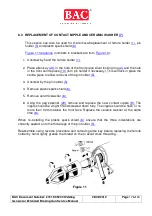
For threaded pins the brazing time is the only guideline and this should be set as 

close to one and a half second as is reasonably practical. An even fillet of solder 
around the base of the pin indicates correct conditions. 
 
When the correct result has been achieved note the position of the power dial on 
the  generator  for  future  use.  This  may  not  necessarily  be  near  the  original  40V 
240A setting. 
 
Regularly check the gun lift height as detailed in section 5.2, as repeated use can 
gradually cause the gun to go out of adjustment. 


If the ferrule is not held evenly against the copper lug and is in partial contact then 
the arc can escape out of the gap and this will result in the side of the copper lug 
burning away.  
 

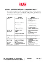
6.1   ACCEPTANCE CRITERIA OF COMPLETED PIN BRAZE 

 
6.1.1    8mm direct brazing pin and cable lug 


Mechanical Strength 


When  the  pin  braze  is  completed  it  should  be  tested  by  firmly  hitting  the 
connection twice with a 1KG hammer (do not hit the shank of the cable lug where 
the cable is crimped). If there is no movement of the cable lug at the connection 
point  then  the  mechanical  integrity  can  be  deemed  acceptable.  Should  there  be 
any movement whatsoever then the connection should be rejected. 


Electrical Integrity  

 
Using  an  Ohm  meter  with  a  4  digit  resolution,  measure  the  resistance  of  the  pin 
braze connection from the cable lug to the pipe. The acceptance criterion is 

  0.010 

.  Note  that  the  test  lead  resistance  should  be  measured  first  and 

deducted from the absolute resistance measurement.  

 
6.1.2    M8, M10 & M12 threaded brazing pin 


Mechanical Strength 

 
Threaded pin attachments should be tested by a torque device. For an M8 pin the 
torque device should be set to 10 Nm. The threads will fail at 25 Nm, so do not use 
excessive  force.  If  there  is  any  movement  of  the  pin  up  to  10  Nm  then  the 
connection should be rejected. 


Содержание 273 199 0240

Страница 1: ...tion Manual Welding Generator Invertor Compatible Pin Brazing Guns Standard Pin Brazing Gun Part 273 199 0240 Extended Pin Brazing Gun Part 273 199 5230 BAC Corrosion Control Ltd Stafford Park 11 Telford Shropshire TF3 3AY Tel 44 0 1952 290321 Fax 44 0 1952 290325 Email sales bacgroup com ...

Страница 2: ...BAC Document Number 273 199 5230 Welding Generator Extended Brazing Gun Service Manual 28 08 2012 Page 2 of 23 ...

Страница 3: ...ATOR 7 5 0 PREPARATION OF THE SURFACE 7 5 1 LOADING THE PIN INTO THE BRAZING GUN 9 5 2 ADJUSTING THE BRAZING GUN 9 5 3 LOCATION OF CONNECTIONS 10 5 4 MAKING A PIN BRAZE 11 6 0 TESTING A COMPLETED BRAZE 13 6 1 ACCEPTANCE CRITERIA OF COMPLETED PIN BRAZE 14 7 0 EQUIPMENT CHECK 15 8 2 REPLACEMENT OF THE CONTACT SET 16 8 3 REPLACEMENT OF CONTACT NIPPLE AND CERAMIC WASHER 17 9 0 FAULT DIAGNOSIS OF UNSAT...

Страница 4: ...de cables to steel inserts and pipelines at pipe coating terminals lay barges and workshops where a large number of brazes are required in a short period of time at a static location It is important that you carefully read and understand this manual and take time to watch the training video supplied with your equipment prior to operating your equipment 2 0 SAFETY 2 1 SYMBOLS USED Read all manuals ...

Страница 5: ...never make any modifications to the equipment or use spare parts and consumables not manufactured or recommended by BAC Never operate the equipment when tired after drinking alcohol taking drugs or taking medication that may make you drowsy Keep bystanders away whilst operating the equipment Do not abuse the cables and connectors and never use the cables for carrying or pulling the equipment Alway...

Страница 6: ...able operation 3 1 SPARE PARTS A full set of spare parts for pin brazing equipment is available off the shelf for immediate despatch We offer a fast and efficient equipment refurbishment repair service using genuine spare parts fitted by expert technicians Most repairs can be completed within a few days keeping expensive downtime to a minimum If you are offered any pin brazing consumables or parts...

Страница 7: ... will be necessary to make some trial brazes and adjust the welding generator output until the set output is achieving an acceptable pin braze A note of the settings should be made for future reference Initially adjust the current output to 240A DC negative earth Adjust the output voltage to 40V DC Load the brazing gun as detailed in section 5 1 Fig 2 Adjust the brazing gun as detailed in section ...

Страница 8: ...lidate the pipe cleaning procedure An area sufficient to accommodate the brazing pin and cable lug must be correctly located and cleaned to a bright metal finish There are many stone and coated abrasive disks available that are suited to pipe surface preparation and that also minimise metal loss To prevent the cleaned metal surface re oxidising we recommend that pin brazing must take place as soon...

Страница 9: ...azing pin which has been inserted and then removed from the gun be re inserted and used for brazing without checking the kinked end profile and fuse wire connection to pin 5 2 ADJUSTING THE BRAZING GUN Before connecting the earth clamp to the steel adjust the brazing pin lift height as follows Hold the copper cable lug flat on the steel surface Insert a loaded brazing pin into the hole in the cabl...

Страница 10: ...ld be accurately marked on the steel Do not use any oil based marker e g spray paint as this will contaminate the grinding burr When pin brazing onto a coated pipeline then sufficient coating needs to be removed in order to accommodate both the earth device and area of the pin braze this would be a minimum of 14 cm x 4 cm using the standard earth device If the earth device is placed on a separate ...

Страница 11: ... the hole in the cable lug Apply sufficient pressure on the brazing gun so that you are overcoming and fully compressing the internal spring and that full contact is made between the ferrule the brazing pin and cable lug onto the substrate For threaded pins it will be the ferrule and the brazing pin When the operator is ready to braze he should look well to one side to protect his eyes from glare ...

Страница 12: ...be withdrawn completely from the work keeping the trigger depressed After the fuse has ruptured the gun must be held in place for at least a further 3 seconds to allow the braze to set Remove the gun by pulling straight off the pipe or substrate in line with the brazed pin then break out the ferrule if this is remaining in the ferrule holder This can be achieved by levering against a suitable edge...

Страница 13: ...ure 8 indicates that too much current is being drawn Therefore adjust the generator output down in 10 amp increments and make test brazes until the result is as figure 3 However if the acceptance criteria is achieved as detailed is 6 1 then the connection may be acceptable provided it is not continually repeated Figure 9 indicates that too little current is being drawn Therefore adjust the generat...

Страница 14: ...IN BRAZE 6 1 1 8mm direct brazing pin and cable lug Mechanical Strength When the pin braze is completed it should be tested by firmly hitting the connection twice with a 1KG hammer do not hit the shank of the cable lug where the cable is crimped If there is no movement of the cable lug at the connection point then the mechanical integrity can be deemed acceptable Should there be any movement whats...

Страница 15: ...ing period to carry out the necessary checks and servicing required Carrying out these procedures will prevent time wasted on site when work is aborted due to faulty equipment Time and personnel must also be allocated to the general servicing of equipment on a routine basis If the servicing procedures have been correctly carried out and a problem still exists contact the Technical Service Engineer...

Страница 16: ...un cable 27 ensure the spring washer is removed 2 Unscrew the domed contact and remove from the contact arm 25 ensure the spring washer is removed 8 2 2 Re assembly 1 Screw the domed contact into the spring bracket 23 Ensure that the spring washer is located correctly in the groove in the contact before tightening Do not over tighten the contacts 2 Place the flat contact through the hole in the gu...

Страница 17: ...ary This will lock in place the centre piece to allow removal of the pin holder 5 3 Unscrew by the pin holder 5 4 Remove plastic spark shield 6 5 Remove ceramic washer 8 6 Using the peg spanner 29 remove and replace the new contact nipple 9 The nipple should be a tight fit and screwed down fully The nipple should be flush or no more than 0 2mm below the front face Replace the ceramic washer at the...

Страница 18: ...tor switched off Worn Contacts Trigger malfunction Check fuse wire on pin is engaged Check earth lead is connected Switch on generator Replace Contacts Check and repair or replace trigger assembly Arc time too short fig 4 Excessive current drawn Poor earth connection Adjust generator power down Check setting of gun Improve earth connection Arc time too long fig 5 Insufficient current drawn Adjust ...

Страница 19: ...threaded brazing pins 12 273 190 0580 Ejector Rod Complete For Standard Gun 2 273 190 0560 Front Piece complete with locking ring 12 273 190 4580 Extended Ejector Rod Complete For Extended Gun 4 270 074 8160 Locking Ring 16 270 071 5340 Remanence Washer 5 270 071 5600 Pin Holder for 8mm direct brazing pins 17 273 190 0590 Conductor Ring and Insulating Ring 273 100 0550 Pin Holder for M8 threaded b...

Страница 20: ...ries to the respective collection point where the electrical appliance or batteries will be recycled The places where the used electrical appliances are collected exist in the European Union and in other European countries as well By proper disposal of the product you can prevent possible negative impact on the environment and human health which might otherwise occur as a consequence of improper m...

Страница 21: ...BAC Document Number 273 199 5230 Welding Generator Extended Brazing Gun Service Manual 28 08 2012 Page 21 of 23 NOTES ...

Страница 22: ...BAC Document Number 273 199 5230 Welding Generator Extended Brazing Gun Service Manual 28 08 2012 Page 22 of 23 NOTES ...

Страница 23: ... 199 5230 Welding Generator Extended Brazing Gun Service Manual 28 08 2012 Page 23 of 23 BAC Corrosion Control Ltd Stafford Park 11 Telford Shropshire TF3 3AY Tel 44 0 1952 290321 Fax 44 0 1952 290325 Email sales bacgroup com ...

Отзывы: